Release Info Tekla Structures 2019
2019
Tekla Structures
Environment
Netherlands
South America
Spain
Release Info 2019 includes the following topics:
General
Tekla Structures 2019 videos
Tekla Structures provides many new options, improvements and fixes. These are all explained in this Release Info. Besides, some videos are available in which these functionalities are explained.

You can check the following videos (per segment):
Steel Detailing
Precast
Cast in Place
Engineering
Image
You can check the following videos (per segment):
Steel Detailing
Precast
Cast in Place
Engineering
Updated start screen
The Tekla Structures 2019 has been updated.
1. All tabs of the start screen now have their own dedicated views:

2. There is a new Shared models tab that includes the Tekla Model Sharing models. If you want to open a model that has been shared by using Tekla Model Sharing, you need to be logged in with your Trimble Identity.
3. When you select a model on the Recent or on the All models tab, and the selected model does not have a thumbnail yet, a hyperlink is shown. When you click the hyperlink, Tekla Structures displays a message which gives instructions on how to create a thumbnail.
4. When you select a model on the Recent or on the All models tab, the Open button has a small arrow that opens a drop-down menu that contains the Convert to multi-user model, Convert to single-user model or Exclude from sharing button, depending on the type of the model.
5. On the Recent and All models tabs, you can sort each of the columns. Additionally, you can change the order and size of the columns by dragging them.
6. If the Recent tab is empty, then the All models tab is shown.
7. If the All models tab is empty, then the New tab is shown.
8. If you want to remove a model from the list of models on the Recent tab, right-click a model and select one of the options.
- Delete the selected item: remove the selected model from the list.
- Clear all: remove all the models from the list.
- Clear invalid entries: remove all invalid models from the list, such as deleted models that cannot be opened anymore.
9. On the New tab, you can hide the model templates that you do not need or mark the important templates as favorites.
- Select a model template in the list.
- Right-click and select Favorite or Hidden.
If you marked a template as Favorite, it is placed on top of the template list. Alternatively, use the star icon
 on the template to mark it as Favorite, or to remove the marking. If you marked a template as Hidden, it is removed from the template list. Select the Show hidden items check box to show it again.
10. If you have collapsed the side sections, such as Your current Tekla Structures setup and Notifications, the side sections now remember their collapsed state.
1. All tabs of the start screen now have their own dedicated views:
Image
2. There is a new Shared models tab that includes the Tekla Model Sharing models. If you want to open a model that has been shared by using Tekla Model Sharing, you need to be logged in with your Trimble Identity.
3. When you select a model on the Recent or on the All models tab, and the selected model does not have a thumbnail yet, a hyperlink is shown. When you click the hyperlink, Tekla Structures displays a message which gives instructions on how to create a thumbnail.
4. When you select a model on the Recent or on the All models tab, the Open button has a small arrow that opens a drop-down menu that contains the Convert to multi-user model, Convert to single-user model or Exclude from sharing button, depending on the type of the model.
5. On the Recent and All models tabs, you can sort each of the columns. Additionally, you can change the order and size of the columns by dragging them.
6. If the Recent tab is empty, then the All models tab is shown.
7. If the All models tab is empty, then the New tab is shown.
8. If you want to remove a model from the list of models on the Recent tab, right-click a model and select one of the options.
- Delete the selected item: remove the selected model from the list.
- Clear all: remove all the models from the list.
- Clear invalid entries: remove all invalid models from the list, such as deleted models that cannot be opened anymore.
9. On the New tab, you can hide the model templates that you do not need or mark the important templates as favorites.
- Select a model template in the list.
- Right-click and select Favorite or Hidden.
If you marked a template as Favorite, it is placed on top of the template list. Alternatively, use the star icon
Image
10. If you have collapsed the side sections, such as Your current Tekla Structures setup and Notifications, the side sections now remember their collapsed state.
Renewed user interface
Tekla Structures 2019 includes a renewed user interface in which the colors have changed. This gives more contrast to the functionalities in the ribbon for example and in the menu File:

Image
Project properties modified
The Project properties in Tekla Structures 2019 include some new text fields (1). You start modifying the text fields without first enabling the editing:

When you have modified the Project properties, the Modify button becomes active automatically. Click Modify (2) to apply the changes.
Image
When you have modified the Project properties, the Modify button becomes active automatically. Click Modify (2) to apply the changes.
Set the ribbon font size
You can now resize the ribbon font size. Use the Font size (Ribbon) slider in File > Settings > User interface to adjust the ribbon font size:

You can set the ribbon font size between 9p and 14p. The default font size is 11p. The setting is remembered for all models when you close and start Tekla Structures.
Image
| Font size: Image
Image
 |
| Font size: Image
Image
 |
| Font size: Image
Image
 |
You can set the ribbon font size between 9p and 14p. The default font size is 11p. The setting is remembered for all models when you close and start Tekla Structures.
Side pane extended
Tekla Structures now opens only one side pane window at a time by default. When you right-click a side pane button, you can select whether to use the Single pane or the Stacked panes option:

- Single pane: Tekla Structures opens a new side pane window and closes all the other open side pane windows.
- Stacked panes: Tekla Structures opens a new side pane window and keeps the other open side pane windows stacked on top of each other.
To open only one side pane, even if the option Stacked panes is set, you click Ctrl + side pane button.
Image
- Single pane: Tekla Structures opens a new side pane window and closes all the other open side pane windows.
- Stacked panes: Tekla Structures opens a new side pane window and keeps the other open side pane windows stacked on top of each other.
To open only one side pane, even if the option Stacked panes is set, you click Ctrl + side pane button.
Quick Launch improved
Quick Launch has been improved and redesigned for Tekla Structures 2019:

1. Now the search results show the location of the command, and the commands are listed by the location. You can easily navigate in the search results by clicking the Recent, Ribbon, Menu, and All commands tabs. The Recent tab list the 10 most recently started commands from the search results, making it easier to access the most used commands repeatedly.
2. The search box is not cleared automatically anymore when you select a command from the search results list. The search word remains visible and when you click the search box, the previous search results list opens automatically. To clear the Quick Launch box, click the button
 or press the Esc key.

3. If the command you have searched by using Quick Launch is in the side pane, Tekla Structures opens the side pane window if it is not open already.
4. Commands and toolbars that can be switched on or off can now be switched on or off without closing the search results list.
Image
1. Now the search results show the location of the command, and the commands are listed by the location. You can easily navigate in the search results by clicking the Recent, Ribbon, Menu, and All commands tabs. The Recent tab list the 10 most recently started commands from the search results, making it easier to access the most used commands repeatedly.
2. The search box is not cleared automatically anymore when you select a command from the search results list. The search word remains visible and when you click the search box, the previous search results list opens automatically. To clear the Quick Launch box, click the button
Image
Image
3. If the command you have searched by using Quick Launch is in the side pane, Tekla Structures opens the side pane window if it is not open already.
4. Commands and toolbars that can be switched on or off can now be switched on or off without closing the search results list.
Updating model templates
In case you have created model templates in earlier Tekla Structures versions, you must update the templates to use them hassle-free in Tekla Structures 2019.
Click here for the general step plan.
Click here for the general step plan.
Material Catalog extended
The Material catalog has been extended in Tekla Structures 2019. The grades 5.8, 10.9, AISI304, AISI316, GS-25CrNiMo4 VI, S235JRH, S275J0H, S355J2+N, S355J2H and S355JO are added to the group Steel (File > Catalogs > Material catalog):

Furthermore, the density for strip steel is changed from 8000 kg/m3 to 2800 kg/m3:

Image
Furthermore, the density for strip steel is changed from 8000 kg/m3 to 2800 kg/m3:
Image
Bolt Assembly Catalog modified
The Bolt assembly catalog is modified in Tekla Structures 2019. The Bolt assemblies 601, 603, 912, 931, 933, 6914, 7968 and 7991 (old DIN-standards) are deleted from the bolt assembly catalog. The catalog now only includes bolt assemblies according to the ISO-standard:

Furthermore, the existing bolt assemblies ZINC, TAPPED_HOLE, WALL_TIES, SCREWANCHOR-MMS-S, WOOD_BOLT-EGAL and WOOD_BOLT-HGAL are modified to only use the ISO-standard for the elements of the bolt assemblies:

When you use your own modified bolt assembly catalog in Tekla Structures (file assdb.db stored in the folder ts), you can check whether you want to make use of your "old" catalog instead of the new standard bolt assembly catalog in Tekla Structures 2019.
You can also export your own modifications from the bolt assembly catalog and import these in the new standard Tekla Structures 2019 bolt assembly catalog.
Click here for more detailed information.
Image
Furthermore, the existing bolt assemblies ZINC, TAPPED_HOLE, WALL_TIES, SCREWANCHOR-MMS-S, WOOD_BOLT-EGAL and WOOD_BOLT-HGAL are modified to only use the ISO-standard for the elements of the bolt assemblies:
Image
When you use your own modified bolt assembly catalog in Tekla Structures (file assdb.db stored in the folder ts), you can check whether you want to make use of your "old" catalog instead of the new standard bolt assembly catalog in Tekla Structures 2019.
You can also export your own modifications from the bolt assembly catalog and import these in the new standard Tekla Structures 2019 bolt assembly catalog.
Click here for more detailed information.
Copy customized ribbon and shortcuts to Tekla Structures 2019
You can copy your customized ribbon and shortcuts (after installing Tekla Structures 2019) from an older Tekla Structures version to Tekla Structures 2019.
Copy the ribbon
1. In the Windows Explorer, go to the folder
2. The *.xml file:
3. Copy this *.xml file to the folder
Click here for more detailed information about copying the ribbon.
Click here for more information about comparing the original ribbon with the changes you have made.
Copy shortcuts
To copy shortcuts from an earlier Tekla Structures version to Tekla Structures 2019:
1. In an earlier Tekla Structures version, go to File > Settings > Keyboard shortcuts.
2. Click on the button Export, save the *.xml file on the desired location with the desired name.
3. In Tekla Structures 2019, go to File > Settings > Keyboard shortcuts.
4. Click on the button Import, select the *.xml file and click on the button Open, the shortcuts are now imported.
You can copy the exported *.xml file to any computer and next import the file in Tekla Structures 2019.
Copy the ribbon
1. In the Windows Explorer, go to the folder
C:\Users\<user>\AppData\Local\Trimble\TeklaStructures\<versie>\UI\Ribbons\2. The *.xml file:
albl_up_<license>--main_menu.xml contains the customized ribbon.3. Copy this *.xml file to the folder
C:\Users\<user>\AppData\Local\Trimble\Tekla Structures\2019.0\UI\Ribbons.Click here for more detailed information about copying the ribbon.
Click here for more information about comparing the original ribbon with the changes you have made.
Copy shortcuts
To copy shortcuts from an earlier Tekla Structures version to Tekla Structures 2019:
1. In an earlier Tekla Structures version, go to File > Settings > Keyboard shortcuts.
2. Click on the button Export, save the *.xml file on the desired location with the desired name.
3. In Tekla Structures 2019, go to File > Settings > Keyboard shortcuts.
4. Click on the button Import, select the *.xml file and click on the button Open, the shortcuts are now imported.
You can copy the exported *.xml file to any computer and next import the file in Tekla Structures 2019.
Changed folder structure
The folder structure has been changed in Tekla Structures 2019 and is now more clear:

Tekla Structures 2018i and earlier versions Tekla Structures 2019
The location of the folders has changed: the folders are now divided per configuration (1) to structure these and make it easier to find the needed folder(s). Besides the files are now stored in the logical sub folders (2). The folder General includes general settings, used for all configurations. These files are also divided per sub folder. The default location for the folder ts has not changed.
Image
Tekla Structures 2018i and earlier versions Tekla Structures 2019
The location of the folders has changed: the folders are now divided per configuration (1) to structure these and make it easier to find the needed folder(s). Besides the files are now stored in the logical sub folders (2). The folder General includes general settings, used for all configurations. These files are also divided per sub folder. The default location for the folder ts has not changed.
Environment Netherlands_enu changed
The additional environment netherlands_enu, available in earlier Tekla Structures versions, has been renamed to construsofteuropean in Tekla Structures 2019.
The environment construsofteuropean is equal to the environment netherlands, however it is translated to English.

Tekla Structures 2018i and earlier Tekla Structures 2019
The folder structure of the environment construsofteuropean is equal to the environment netherlands.
The environment construsofteuropean is equal to the environment netherlands, however it is translated to English.
Image
Tekla Structures 2018i and earlier Tekla Structures 2019
The folder structure of the environment construsofteuropean is equal to the environment netherlands.
VMU-profile modified
The parametric profile VMU is improved in Tekla Structures 2019 and now creates a correct thickness for the profile in all directions:

Image
Interoperability
Exporting Tekla Structures models to Trimble Connect
In Tekla Structures you can now export the model to an IFC file and next open it in Trimble Connect:

Tekla Structures Trimble Connect
Trimble Connect enables collaboration for engineering and construction projects and is accessible via Desktop, Mobile or Web. Trimble Connect allows you to view, share, and access project information from anywhere at any time. You can combine 2D and 3D file formats, such as IFC, STEP, DWG and SKP. You can even add annotations in Trimble Connect.
Tekla Structures 2019 no longer includes the command to export your Tekla Structures model direct to Tekla BIMsight. You can still export your Tekla Structures model to an IFC file and open it Tekla BIMsight. However, Tekla BIMsight is approaching its end-of-life by the end of 2019. As of December 31, 2019, we discontinue to distribute, support and maintain Tekla BIMsight. You can still use it after that date.
Collaborate in Trimble Connect
The following Trimble Connect versions are available (you possibly need to log in with your Trimble Identity):
- Trimble Connect Web, this is the online version (In Tekla Structures via tab Trimble Connect > Web).
- Trimble Connect Desktop, click here for the download (In Tekla Structures via tab Trimble Connect > Desktop).
Click here for an instruction video about the usage of Trimble Connect Desktop.
Step plan
1. Open a Tekla Structures model.
2. Before exporting the Tekla Structures model, check whether the parts you want to export, do include the correct IFC-entity and IFC-export type.
3. If needed, create a base point in your model for the IFC file, click here for more detailed information.
5. Select the entire model or select the model objects that you want to export.
6. Click File > Export > IFC, dialog box Export to IFC appears:

7. If needed, you can define property set configuration files (field Additional property sets) besides the predefined property set configuration files to define which user-defined attributes are exported as property sets into IFC models. Click here for more detailed information.
8. Click Export, the IFC file is created and stored in the model folder by default.
9. Open Trimble Connect, if needed log in with your Trimble Identity.
10. Click on the button New project, enter the name for the project and click on the button Create project:

11. Next add the IFC file to the project by dragging it from the Windows Explorer into Trimble Connect:

12. Double-click on the 3D View open the IFC file:

Note: Tekla Structures 2019 also includes a new command to export directly to Trimble Connect via File > Export > Trimble Connect. However, you do not use the command; you follow the step plan above.
Click here for detailed information about Trimble Connect.
Click here for an instruction video about the collaboration between Tekla Structures and Trimble Connect.
Tool Linking Documents to Trimble Connect
You can use the tool Linking Documents to Trimble Connect in Tekla Structures:

The tool is available in Tekla Warehouse and automatically links drawings (assembly, cast unit and single part) and other documents to an IFC objects in an existing Trimble Connect model:

Please note that the tool Linking Documents to Trimble Connect is only compatible till Tekla Structures version 2018i, (not) yet for Tekla Structures 2019.
Click here for detailed information about the usage of the tool Linking Documents to Trimble Connect.
Image
Tekla Structures Trimble Connect
Trimble Connect enables collaboration for engineering and construction projects and is accessible via Desktop, Mobile or Web. Trimble Connect allows you to view, share, and access project information from anywhere at any time. You can combine 2D and 3D file formats, such as IFC, STEP, DWG and SKP. You can even add annotations in Trimble Connect.
Tekla Structures 2019 no longer includes the command to export your Tekla Structures model direct to Tekla BIMsight. You can still export your Tekla Structures model to an IFC file and open it Tekla BIMsight. However, Tekla BIMsight is approaching its end-of-life by the end of 2019. As of December 31, 2019, we discontinue to distribute, support and maintain Tekla BIMsight. You can still use it after that date.
Collaborate in Trimble Connect
The following Trimble Connect versions are available (you possibly need to log in with your Trimble Identity):
- Trimble Connect Web, this is the online version (In Tekla Structures via tab Trimble Connect > Web).
- Trimble Connect Desktop, click here for the download (In Tekla Structures via tab Trimble Connect > Desktop).
Click here for an instruction video about the usage of Trimble Connect Desktop.
Step plan
1. Open a Tekla Structures model.
2. Before exporting the Tekla Structures model, check whether the parts you want to export, do include the correct IFC-entity and IFC-export type.
3. If needed, create a base point in your model for the IFC file, click here for more detailed information.
5. Select the entire model or select the model objects that you want to export.
6. Click File > Export > IFC, dialog box Export to IFC appears:
Image
7. If needed, you can define property set configuration files (field Additional property sets) besides the predefined property set configuration files to define which user-defined attributes are exported as property sets into IFC models. Click here for more detailed information.
8. Click Export, the IFC file is created and stored in the model folder by default.
9. Open Trimble Connect, if needed log in with your Trimble Identity.
10. Click on the button New project, enter the name for the project and click on the button Create project:
Image
11. Next add the IFC file to the project by dragging it from the Windows Explorer into Trimble Connect:
Image
12. Double-click on the 3D View open the IFC file:
Image
Note: Tekla Structures 2019 also includes a new command to export directly to Trimble Connect via File > Export > Trimble Connect. However, you do not use the command; you follow the step plan above.
Click here for detailed information about Trimble Connect.
Click here for an instruction video about the collaboration between Tekla Structures and Trimble Connect.
Tool Linking Documents to Trimble Connect
You can use the tool Linking Documents to Trimble Connect in Tekla Structures:
Image
The tool is available in Tekla Warehouse and automatically links drawings (assembly, cast unit and single part) and other documents to an IFC objects in an existing Trimble Connect model:
Image
Please note that the tool Linking Documents to Trimble Connect is only compatible till Tekla Structures version 2018i, (not) yet for Tekla Structures 2019.
Click here for detailed information about the usage of the tool Linking Documents to Trimble Connect.
Modeling
Modeling radial grids
In Tekla Structures 2019 you can create truly radial grids by using the new command Create radial grid
 :
:

If needed, you can create a full 360-degree grid. To create a radial grid:
1. On the Edit tab, click Grid > Create radial grid. Tekla Structures shows a preview of the grid.
You can modify the Radial grid properties in the property pane before inserting the grid. The grid preview changes according to the changes in the property pane.
2. Pick a point in the model to indicate the origin of the grid or click the middle mouse button to accept the Radial grid property pane values.
- If you pick an origin point to the grid, the grid is created using the properties in the property pane and the origin is the location you picked.
- If you click the middle mouse button, the grid is created using the properties in the property pane and to the origin defined in the property pane.
Modify radial grid
In addition to the Radial grid properties in the property pane, you can use direct modification and the contextual toolbar to modify radial grids. Ensure that Direct modification is switched on.
- You can drag the arc lines to change the radius.

- You can drag the straight lines to change the angle.

- You can add new grid lines between the existing grid lines, both arc lines and straight lines.

- You can change the grid labels by using the contextual toolbar.

Click here for a video about modeling radial grids.
Image
Image
If needed, you can create a full 360-degree grid. To create a radial grid:
1. On the Edit tab, click Grid > Create radial grid. Tekla Structures shows a preview of the grid.
You can modify the Radial grid properties in the property pane before inserting the grid. The grid preview changes according to the changes in the property pane.
2. Pick a point in the model to indicate the origin of the grid or click the middle mouse button to accept the Radial grid property pane values.
- If you pick an origin point to the grid, the grid is created using the properties in the property pane and the origin is the location you picked.
- If you click the middle mouse button, the grid is created using the properties in the property pane and to the origin defined in the property pane.
Modify radial grid
In addition to the Radial grid properties in the property pane, you can use direct modification and the contextual toolbar to modify radial grids. Ensure that Direct modification is switched on.
- You can drag the arc lines to change the radius.
Image
- You can drag the straight lines to change the angle.
Image
- You can add new grid lines between the existing grid lines, both arc lines and straight lines.
Image
- You can change the grid labels by using the contextual toolbar.
Image
Click here for a video about modeling radial grids.
Grid properties in the property pane
Lots of model object properties (such as columns and beams) were already available in the property pane in Tekla Structures.
Now the properties of rectangular grids, radial grids, and single grid lines are accessed through the property pane:

The grid properties now include Grid color and Label font size and color. Previously, these were available in advanced options.
Now the properties of rectangular grids, radial grids, and single grid lines are accessed through the property pane:
Image
The grid properties now include Grid color and Label font size and color. Previously, these were available in advanced options.
Improved representation for welded RHS profiles in model views
Since Tekla Structures 2018i, the representation for welded plates in model views has been improved. Welded plates color light blue, loose plates don't:

Tekla Structures 2018i
In Tekla Structures 2019, the corresponding default model view settings have been improved further:

...to also improve the representation for welded RHS profiles:

If desired, you can customize the default model view settings (even further), for example to represent RHS profiles till a specific length:

Image
Tekla Structures 2018i
In Tekla Structures 2019, the corresponding default model view settings have been improved further:
Image
...to also improve the representation for welded RHS profiles:
Image
If desired, you can customize the default model view settings (even further), for example to represent RHS profiles till a specific length:
Image
New PDF reports available
Tekla Structures 2019 includes several new "wood" related PDF reports:

To open these reports after creating them directly, select the following option:


Mind that the file size of pdf reports can be quite big, this of course depends on the number of objects in the pdf file.
If required, you can choose to print the created reports (pdf files) again with your own pdf printer (Win2pdf for example). This decreases the file size significant.
Image
To open these reports after creating them directly, select the following option:
Image
Image
Image
Mind that the file size of pdf reports can be quite big, this of course depends on the number of objects in the pdf file.
If required, you can choose to print the created reports (pdf files) again with your own pdf printer (Win2pdf for example). This decreases the file size significant.
Modeling stand-alone bent plates
You can now create stand-alone bent plates that do not require any input parts. Use stand-alone bent plates to model both cylindrical and conical parts, such as hoods, hoppers, cones, and so on.

To set the accuracy (number of segments) for bent plates, click here.
Before you start to create stand-alone bent plates, ensure that Direct modification
 is switched on.
Step plan
1. On the Steel tab, click Plate > Create stand-alone bent plate
 .
.
2. Define the first radius of the bend.
a. Pick the center point (1).
b. Pick the start point for the arc (2).
c. Pick the end point for the arc (3).

The picking order defines the up direction. For example, if you create an arc on the xy plane in the counter clockwise direction, the up direction points to the positive z axis, according to the right-hand rule.
3. Pick a point to define the height of the bend.

Alternatively, you can enter the height in the bent plate contextual toolbar (4).
4. Define the second radius of the bend.
a. Pick a point based on the preview of the plate.
If you want to change the direction of the plate after you have picked a point, click the left mouse button.

Alternatively, if you want to create a cylindrical bend, click the middle mouse button. In this case radius1=radius2.
5. To complete the bent plate creation, click the middle mouse button.

Modify the shape of a stand-alone bent plate
Use direct modification dimension values and handles to modify the bent plate shape.

You can change the angle, radiuses and height of the bend by entering new dimension values, you can drag and stretch the edges of the bent plate and add and delete intermediate points.
Besides you can create unfolded drawings of the stand-alone bent plates: you can use the setting unfolded in the single-part drawing properties:

Click here for a video about modeling stand-alone bend plates.
Image
To set the accuracy (number of segments) for bent plates, click here.
Before you start to create stand-alone bent plates, ensure that Direct modification
Image
Step plan
1. On the Steel tab, click Plate > Create stand-alone bent plate
Image
2. Define the first radius of the bend.
a. Pick the center point (1).
b. Pick the start point for the arc (2).
c. Pick the end point for the arc (3).
Image
The picking order defines the up direction. For example, if you create an arc on the xy plane in the counter clockwise direction, the up direction points to the positive z axis, according to the right-hand rule.
3. Pick a point to define the height of the bend.
Image
Alternatively, you can enter the height in the bent plate contextual toolbar (4).
4. Define the second radius of the bend.
a. Pick a point based on the preview of the plate.
If you want to change the direction of the plate after you have picked a point, click the left mouse button.
Image
Alternatively, if you want to create a cylindrical bend, click the middle mouse button. In this case radius1=radius2.
5. To complete the bent plate creation, click the middle mouse button.
Image
Modify the shape of a stand-alone bent plate
Use direct modification dimension values and handles to modify the bent plate shape.
Image
You can change the angle, radiuses and height of the bend by entering new dimension values, you can drag and stretch the edges of the bent plate and add and delete intermediate points.
Besides you can create unfolded drawings of the stand-alone bent plates: you can use the setting unfolded in the single-part drawing properties:
Image
Click here for a video about modeling stand-alone bend plates.
New Model search toolbar
Tekla Structures 2019 includes the new Model search toolbar to quickly search for objects in the entire model:

You can search by using name, profile, material, position number of model objects: the corresponding model objects are selected automatically in the model view. You can use search terms and wildcards to run a search in the model.
Examples

An empty Model search toolbar: all parts are selected (Ctrl + A) in the model view.


Click here for more information about how to use wildcards.
Tip: To easily find parts in the model views, preferably set the representation for parts to almost completely transparent by using shortcut Ctrl + 5 for parts and shortcut Shift + 5 for component parts.
In case toolbar Model search is switched off, you can use Quick search to switch the toolbar on again.

Image
You can search by using name, profile, material, position number of model objects: the corresponding model objects are selected automatically in the model view. You can use search terms and wildcards to run a search in the model.
Examples
Image
An empty Model search toolbar: all parts are selected (Ctrl + A) in the model view.
Image
Image
Image
Click here for more information about how to use wildcards.
Tip: To easily find parts in the model views, preferably set the representation for parts to almost completely transparent by using shortcut Ctrl + 5 for parts and shortcut Shift + 5 for component parts.
In case toolbar Model search is switched off, you can use Quick search to switch the toolbar on again.
Image
New construction objects available
Tekla Structures 2019 introduces the new construction objects Arc and Polycurve and a new command Copy with offset. Construction objects Line and Circle have been improved.

Click here for a video about the new construction objects.
Image
Click here for a video about the new construction objects.
Arc
To create a construction arc:
1. On the Edit tab, click Construction object > Arc
 :
:
2. On the contextual toolbar that appears, click a button to specify which set of points you want to pick:

- Click
 and then pick three points: the center point, start point, and end point of the arc. You can also define the angle or the length of the arc.
- Click
 and then pick the start point, end point, and an optional point along the arc.
- Click
 and then pick a point to define a tangent, and two points along the arc. Tekla Structures creates the arc using the points you picked and using the current properties Tekla Structures also indicates the center point of the arc with an X in the model.
3. To end the command, press Esc.
4. To modify the construction arc properties, double-click the arc in the model. The arc properties are shown in the property pane. Select a color and a line type for the arc:

5. Click Modify to apply the changes. Tekla Structures uses the new properties the next time you create an object of this type.
6. Switch Direct modification on to modify the arc:

...select the arc... ...to modify the radius... ...or to modify the shape of the arc by dragging the points...
1. On the Edit tab, click Construction object > Arc
Image
2. On the contextual toolbar that appears, click a button to specify which set of points you want to pick:
Image
- Click
Image
- Click
Image
- Click
Image
3. To end the command, press Esc.
4. To modify the construction arc properties, double-click the arc in the model. The arc properties are shown in the property pane. Select a color and a line type for the arc:
Image
5. Click Modify to apply the changes. Tekla Structures uses the new properties the next time you create an object of this type.
6. Switch Direct modification on to modify the arc:
Image
...select the arc... ...to modify the radius... ...or to modify the shape of the arc by dragging the points...
Polycurve
To create a construction polycurve:
1. On the Edit tab, click Construction object > Polycurve
 :
:
2. On the contextual toolbar that appears, click a button to specify which set of points you want to pick to create a polycurve segment. You can switch between these picking modes each time you complete a segment.

- For a straight segment, click the first button Create line
 and then pick the start point and the end point of the segment.
- For a curved segment, click
 and then pick three points along the segment.
- For a curved tangential segment, click
 and then pick a point on the tangent line, the start point, and the end point of the segment.
- For a straight segment that is tangential to the previous segment, click the last button
 Create tangent line and then pick a point on the tangent line. Tekla Structures creates a polycurve segment.
3. Repeat step 2 for each polycurve segment that you want to create, but skip picking the first point of the segment as it is the same as the last point of the previous segment.
4. Click the middle mouse button to finish picking. Tekla Structures creates the polycurve through the points you picked, using the polycurve's current properties.
5. To end the command, press Esc.
6. To modify the construction polycurve properties, double-click the polycurve in the model. The polycurve properties are shown in the property pane. Select a color and a line type for the polycurve:

7. Click Modify to apply the changes. Tekla Structures uses the new properties the next time you create an object of this type.
8. Switch Direct modification on to modify the arc:

1. On the Edit tab, click Construction object > Polycurve
Image
2. On the contextual toolbar that appears, click a button to specify which set of points you want to pick to create a polycurve segment. You can switch between these picking modes each time you complete a segment.
Image
- For a straight segment, click the first button Create line
Image
- For a curved segment, click
Image
- For a curved tangential segment, click
Image
- For a straight segment that is tangential to the previous segment, click the last button
Image
3. Repeat step 2 for each polycurve segment that you want to create, but skip picking the first point of the segment as it is the same as the last point of the previous segment.
4. Click the middle mouse button to finish picking. Tekla Structures creates the polycurve through the points you picked, using the polycurve's current properties.
5. To end the command, press Esc.
6. To modify the construction polycurve properties, double-click the polycurve in the model. The polycurve properties are shown in the property pane. Select a color and a line type for the polycurve:
Image
7. Click Modify to apply the changes. Tekla Structures uses the new properties the next time you create an object of this type.
8. Switch Direct modification on to modify the arc:
Image
Copy with offset
You can copy construction lines, circles, arcs, and polycurves in the direction that you indicate, and using the offset values that you specify. For example, you can create new circles and arcs centered in the same location as the original circle or arc, and adjust the radiuses using the offset values.
1. On the Edit tab, click Construction object > Copy with offset
 :
:
2. Select the construction object that you want to copy. You can copy lines, circles, arcs and polycurves.
3. Enter the offset values in the box that appears, and then press Enter.
If you only enter one offset value, Tekla Structures creates one copy of the object.
To create several copies, enter multiple offset values. For example,
4. Click in the direction where you want to copy the object. Tekla Structures copies the selected object in the direction you indicated.

1. On the Edit tab, click Construction object > Copy with offset
Image
2. Select the construction object that you want to copy. You can copy lines, circles, arcs and polycurves.
3. Enter the offset values in the box that appears, and then press Enter.
If you only enter one offset value, Tekla Structures creates one copy of the object.
To create several copies, enter multiple offset values. For example,
500 1000 1500 or 3*500.4. Click in the direction where you want to copy the object. Tekla Structures copies the selected object in the direction you indicated.
Image
Modify construction objects
You can now change a construction line to an arc. Just drag the arc symbol
 at the line midpoint.
To change a construction arc to a line, delete the arc midpoint.
Image
To change a construction arc to a line, delete the arc midpoint.
Improvements in construction circles and lines
The command Edit > Construction object > Circle replaces the two previous commands Circle using center point and radius and Circle using three points. You can now specify using the contextual toolbar which three points you want to pick in the 3D space in the model to create a construction circle. The contextual toolbar appears after you have started the command.

Besides you can now change the line type of the construction lines and circles using their property panes:

The advanced options
Image
Besides you can now change the line type of the construction lines and circles using their property panes:
Image
The advanced options
XS_CONSTRUCTION_LINE_LINE_TYPE and XS_CONSTRUCTION_CIRCLE_LINE_TYPE that were previously used for changing the line types have now been removed.New part label options in model views
Tekla Structures 2019 includes new options for showing part labels in model views.
1. Double-click a model view, dialog box View Properties appears.
2. Next press the button Display, dialog box Display appears.
3. Click on the tab Advanced:

In the list box you can select for which parts you want to show the part labels.
Note that if you select the Selected or the Main part for selected option, you need to first apply the changes to the view when the view is selected. Then continue to select the objects for which you want to show the part labels.
You can for example define to show Assembly positions and Part positions:

All: Part labels are shown for all parts in the model view:

Selected: Part labels are only shown for the parts you select:

Main part for selected: Part labels are only shown for the main parts of the assemblies you select.

Main part for all: Part labels are shown for all main parts of all assemblies.

1. Double-click a model view, dialog box View Properties appears.
2. Next press the button Display, dialog box Display appears.
3. Click on the tab Advanced:
Image
In the list box you can select for which parts you want to show the part labels.
Note that if you select the Selected or the Main part for selected option, you need to first apply the changes to the view when the view is selected. Then continue to select the objects for which you want to show the part labels.
You can for example define to show Assembly positions and Part positions:
Image
All: Part labels are shown for all parts in the model view:
Image
Selected: Part labels are only shown for the parts you select:
Image
Main part for selected: Part labels are only shown for the main parts of the assemblies you select.
Image
Main part for all: Part labels are shown for all main parts of all assemblies.
Image
Improvements in bolt holes
There is now a new option in the Bolt properties that you can use to specify which plies of the connection do not get holes:

1. Go to the Holes section in the Bolt property pane.
2. Next to Parts with slotted holes, select the desired Special hole check boxes.
3. In the Special hole type list, select No hole.
4. Click Modify.
The No hole option is also available for bolts in system and custom components.
Example
You can for example use this option for cladding panels. You want bolts/screws in the panels for your reports and assembling the panels (1) but there are no holes needed in the panels. Besides, if the holes are not on the exact same position in the panels, you would have different numbers for the same panels. Identical panels (in terms of geometry) having different numbers is not desirable.

Click here for a video about modeling bolts without holes.
Image
1. Go to the Holes section in the Bolt property pane.
2. Next to Parts with slotted holes, select the desired Special hole check boxes.
3. In the Special hole type list, select No hole.
4. Click Modify.
The No hole option is also available for bolts in system and custom components.
Example
You can for example use this option for cladding panels. You want bolts/screws in the panels for your reports and assembling the panels (1) but there are no holes needed in the panels. Besides, if the holes are not on the exact same position in the panels, you would have different numbers for the same panels. Identical panels (in terms of geometry) having different numbers is not desirable.
Image
Click here for a video about modeling bolts without holes.
Numbering improvements
In the Numbering setup dialog box (Drawings & Reports > Numbering settings), the name Phase has been changed to Assembly phase:

Now the Assembly phase setting only affects the numbering of assemblies, not the parts. This means that only the assembly phase of assemblies is compared in numbering, not the part phase nor the assembly phase of parts. The option is switched off by default.
Image
Now the Assembly phase setting only affects the numbering of assemblies, not the parts. This means that only the assembly phase of assemblies is compared in numbering, not the part phase nor the assembly phase of parts. The option is switched off by default.
System components
Bolted gusset (11), Tube gusset (20) and Gusseted cross (62)
System components Bolted gusset (11), Tube gusset (20) and Gusseted cross (62) now include a new option to create a weld between the gusset plate and the footplate:

Image
Crancked beam (41)
System component Crancked beam (41) includes a new option to define the size of the space:

Image
Border rebar (92)
System component Border rebar (92) includes a new option. You can now define, while creating the rebars, to check the cast unit for added concrete parts. For that, you have the new option Cast unit geometry on tab Configuration:

Image
Border rebar for single edge (93)
In system component Border rebar single edge (93) you can now also enter negative values for the fields a and b to define the dimensions for the hairpins:

Furthermore, the component includes a new list box to select hairpin 1, hairpin 2 or hairpin 1 and 2.
Because of these new options, a new setting has been added for system component Border rebar single edge (93):


Image
Furthermore, the component includes a new list box to select hairpin 1, hairpin 2 or hairpin 1 and 2.
Because of these new options, a new setting has been added for system component Border rebar single edge (93):
Image
Image
Reinforced Concrete Stair (95)
System component Reinforced Concrete Stair (95) includes a new option the reinforce stringers:

For this, a new tab Stringer bars is available:

Furthermore, system component Reinforced Concrete Stair (95) includes several enhancements such as new rebar shape options in the top and bottom detail of the concrete stair:

Image
For this, a new tab Stringer bars is available:
Image
Furthermore, system component Reinforced Concrete Stair (95) includes several enhancements such as new rebar shape options in the top and bottom detail of the concrete stair:
Image
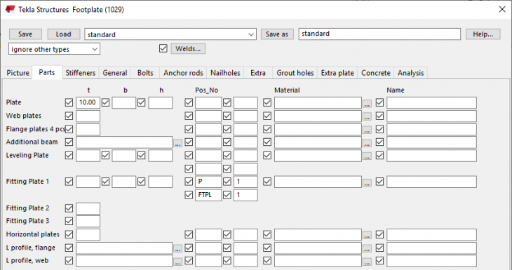
Footplate (1029)
Besides the improvements that have been made in Tekla Structures 2018 and Tekla Structures 2018i for system component Footplate (1029), also Tekla Structures 2019 includes several improvements:
1. The user interface is enhanced, because of this many field are better aligned:
Tekla Structures 2019:
Earlier Tekla Structures versions:

2. A new chamfer option has been added for the footplate on tab Parts:

3. There are new options available on tab Stiffeners for positioning the stiffeners.

4. In case you are using anchors in system component Footplate (1029), the nuts and the washers now automatically rotate in the anchor direction to have identical assemblies/anchor sets with equal numbers:

5. Tab Picture now includes the option Placing to align the footplate and the castplate, especially meant for sloped columns:


When you now model an extra hole as a reference point in the castplate for sloped columns, the position of this extra hole in the castplate is now correct:


6. Tab Bolts now includes a new field Bolt Comment:

Because of this, the by Construsoft provided default settings have been adapted.
1. The user interface is enhanced, because of this many field are better aligned:
Tekla Structures 2019:
Image
Earlier Tekla Structures versions:
Image
2. A new chamfer option has been added for the footplate on tab Parts:
Image
3. There are new options available on tab Stiffeners for positioning the stiffeners.
Image
4. In case you are using anchors in system component Footplate (1029), the nuts and the washers now automatically rotate in the anchor direction to have identical assemblies/anchor sets with equal numbers:
Image
5. Tab Picture now includes the option Placing to align the footplate and the castplate, especially meant for sloped columns:
Image
Image
When you now model an extra hole as a reference point in the castplate for sloped columns, the position of this extra hole in the castplate is now correct:
Image
Image
Image
Image
6. Tab Bolts now includes a new field Bolt Comment:
Image
Because of this, the by Construsoft provided default settings have been adapted.
|
Image
|
In case you have created your own settings for these system components in earlier Tekla Structures versions, please check these settings and modify them if needed to update these for Tekla Structures 2019. |
Bolt comment in several system components
System components Joining plates (14), Stiffened end plate (27), Partial stiff end plate (65), Two sided end plate (142) and End plate (144) now include a new field Bolt Comment on tab Bolts:

Image
Bolt standard and bolt type in several system components
System components Haunch (40) and Cranked beam (41) now include the new fields Bolt standard and Bolt Type on tab Holes:

Image
Drawings
Several improvements in the Document manager
The Document manager includes several improvements in Tekla Structures 2019.
Click here for more detailed information about the Document manager.
Click here for a video about the Document manager.
Document manager layout
The layout of the Document manager is enhanced: the usage of the blue color in the dialog box creates more contrast and improves the representation.
Tekla Structures 2019:

Tekla Structures 2018i:

Tekla Structures 2019:
Image
Tekla Structures 2018i:
Image
Drawing list button name changed to Document manager
On the Drawings & reports tab on the ribbon, the command button name has been changed to Document manager:

In Quick Launch, you can enter either

Image
In Quick Launch, you can enter either
document manager or drawing list. The actual command name is Document manager (drawing list):Image
New indicator for non-editable cells
You can edit data cells directly in the Document manager, for example to modify the drawing name.
1. Ensure that the edit switch
 is active.
2. Select a data cell you wish to edit:

Now when the edit switch is active
 and you hover over a cell that is not editable, the cursor changes to indicate that you cannot edit the cell:

1. Ensure that the edit switch
Image
2. Select a data cell you wish to edit:
Image
Now when the edit switch is active
Image
Image
Organize documents in manual categories
Tekla Structures 2018i already included an option to use categories for documents (such as drawings and reports) in the Document manager based on rules (filter):

Tekla Structures 2019 now includes a new option to also categorize documents manually, for example for drawings because of additional work:

The new option is handy for documents that would be difficult to categorize or in case there is no category available. You can categorize manually or by search.
Creating a manual category may be useful, for example, when you have enabled the Show changes from the checkpoint set when the button is activated
 feature in Document manager, and then when some documents have changed and are listed, you can add the changed documents in a manual category.
All modifications in categories are stored in the file
Image
Tekla Structures 2019 now includes a new option to also categorize documents manually, for example for drawings because of additional work:
Image
The new option is handy for documents that would be difficult to categorize or in case there is no category available. You can categorize manually or by search.
Creating a manual category may be useful, for example, when you have enabled the Show changes from the checkpoint set when the button is activated
Image
All modifications in categories are stored in the file
DocumentManagerCategories_<user>.xml in the current model folder. To make use of modified categories in all Tekla Structures models, you must copy the concerned file to the folder ts and rename the file to DocumentManagerCategories.xml.Sorting order of the columns is improved
The sorting order of the columns in the Document manager is improved and is now correct, it works the same as in the older Drawinglist.
Click here for more detailed information about the Document manager.
Click here for a video about the Document manager.
Change dimension associativity
Dimensioning points created in Tekla Structures are associated to the objects where the dimension points have been added. This allows the dimensions to update automatically when the objects are changed during modeling.
In drawings, the associativity symbol
 indicates which drawing objects are associative and automatically updated. Associativity symbols are shown when you select a drawing object, for example a dimension:

(To hide associativity symbols in drawing views, on the File menu, select Settings > Associativity symbol of press Shift + A).
Objects that do not have valid association get a ghost associativity symbol
 and a question mark.

You can change the dimension point associativity in Tekla Structures 2019 to avoid incorrect associativity, or to simply make the associativity selection distinct. Each dimension point associativity anchor shows a list of objects that have locations available for association. You can change the dimension point associativity in straight dimensions only.

Sometimes the dimension point locations may be unclear due to orthogonal projection. A dimension point might be not be associated to the desired object because there are various other objects in the same point location (sandwich panel). In drawing update or cloning, this may lead to unwanted dimensioning values or associativity.

Change the dimension point associativity rule
1. Select the desired dimension.
2. Click a dimension point associativity anchor. This displays the dimension associativity rule list which shows the objects where the dimension point can be associated. The default associativity rule is automatically selected by Tekla Structures.
3. Click a rule in the list to select it and associate the dimension point to a new object:

When you click the rule, the corresponding object is highlighted in the drawing. This makes it easy for you to check if the selected rule refers to the object you want.
Change the dimension point associativity rule related to same object types
1. Select the desired dimension set:

2. Hold down Alt and use area selection to open all associativity rules related to the selected dimension:

3. Double-click the desired rule to select associativity rules related to same object types in all opened rule lists:

Click here for more detailed information about how to change the dimension point associativity rule.
In drawings, the associativity symbol
Image
Image
(To hide associativity symbols in drawing views, on the File menu, select Settings > Associativity symbol of press Shift + A).
Objects that do not have valid association get a ghost associativity symbol
Image
Image
You can change the dimension point associativity in Tekla Structures 2019 to avoid incorrect associativity, or to simply make the associativity selection distinct. Each dimension point associativity anchor shows a list of objects that have locations available for association. You can change the dimension point associativity in straight dimensions only.
Image
Sometimes the dimension point locations may be unclear due to orthogonal projection. A dimension point might be not be associated to the desired object because there are various other objects in the same point location (sandwich panel). In drawing update or cloning, this may lead to unwanted dimensioning values or associativity.
Image
Change the dimension point associativity rule
1. Select the desired dimension.
2. Click a dimension point associativity anchor. This displays the dimension associativity rule list which shows the objects where the dimension point can be associated. The default associativity rule is automatically selected by Tekla Structures.
3. Click a rule in the list to select it and associate the dimension point to a new object:
Image
When you click the rule, the corresponding object is highlighted in the drawing. This makes it easy for you to check if the selected rule refers to the object you want.
Change the dimension point associativity rule related to same object types
1. Select the desired dimension set:
Image
2. Hold down Alt and use area selection to open all associativity rules related to the selected dimension:
Image
3. Double-click the desired rule to select associativity rules related to same object types in all opened rule lists:
Image
Click here for more detailed information about how to change the dimension point associativity rule.
Dragging drawing objects directly
Tekla Structures 2019 includes a new switch Drawing drag & drop (via File > Settings > Drawing drag & drop) in the Drawing Editor.
You can move drawing objects such as annotations, sketch objects and grid lines without selecting the objects first.

You can also move handle points of sketch objects without first selecting the handles when you have activated Drawing drag & drop: Hold down the left-mouse button close to the handle point and drag the handle point to the new position.
You can move drawing objects such as annotations, sketch objects and grid lines without selecting the objects first.
Image
You can also move handle points of sketch objects without first selecting the handles when you have activated Drawing drag & drop: Hold down the left-mouse button close to the handle point and drag the handle point to the new position.
Dragging dimension points
Straight (linear) dimensions in drawings can now be modified by dragging the dimension points from dimension point handles.

...select a handle ..and drag the handle to another location
Dragging in single dimension lines
If you try to drag a dimension point to a new position that is located behind an existing dimension point, the selected dimension point will be deleted from the old position and recreated in the new, preferred position.
If you try to drag the point to the same coordinate position where the existing point is already located, the dragged dimension point is dropped back automatically to the initial position.
Dragging in dimension sets
If you try to drag the dimension point into the area between two points of neighbour dimension line, the selected dimension point will be deleted from the old position and recreated in the new, preferred position. If you try to drag the point to the same coordinate position where the existing point is already located, the dragged dimension point will be deleted from the old location and will be combined with the existing one, after dropping to the new location.
Image
...select a handle ..and drag the handle to another location
Dragging in single dimension lines
If you try to drag a dimension point to a new position that is located behind an existing dimension point, the selected dimension point will be deleted from the old position and recreated in the new, preferred position.
If you try to drag the point to the same coordinate position where the existing point is already located, the dragged dimension point is dropped back automatically to the initial position.
Dragging in dimension sets
If you try to drag the dimension point into the area between two points of neighbour dimension line, the selected dimension point will be deleted from the old position and recreated in the new, preferred position. If you try to drag the point to the same coordinate position where the existing point is already located, the dragged dimension point will be deleted from the old location and will be combined with the existing one, after dropping to the new location.
Improvements in Drawing content manager
Since Tekla Structures 2018 you can use the interactive tool Drawing content manager
 .
.
Drawing content manager is for checking and editing building objects and drawing content, especially marks, dimension marks, tagged dimension marks and associative notes, in the current drawing.
Click here for more detailed information about the Drawing content manager.
The tool Drawing content manager includes several improvements in Tekla Structures 2019.
1. Several columns have been added by default to the categories (such as Assemblies and Parts) and you can modify these. You can also add new columns to the Drawing content manager. For this, click the next button:

Dialog box Add/Edit properties appears, you can drag the desired property from the left to the right column to add it:

Enter a name for the column as it needs to be displayed in dialog box Drawing content manager, next click OK:

To edit the current properties, select a property and click right mouse button. Next select the command Edit or Remove:

2. You can change the order of the existing columns by simply dragging columns to the new position:

3. Two categories have been added in dialog box Drawing content manager:

4. You can hide category types from the list of visible categories by right clicking Drawing content manager pane when no category is selected and clicking the categories on the displayed list:


To use the modified settings in the Drawing content manager in all models, copy the file
Image
Drawing content manager is for checking and editing building objects and drawing content, especially marks, dimension marks, tagged dimension marks and associative notes, in the current drawing.
Click here for more detailed information about the Drawing content manager.
The tool Drawing content manager includes several improvements in Tekla Structures 2019.
1. Several columns have been added by default to the categories (such as Assemblies and Parts) and you can modify these. You can also add new columns to the Drawing content manager. For this, click the next button:
Image
Dialog box Add/Edit properties appears, you can drag the desired property from the left to the right column to add it:
Image
Enter a name for the column as it needs to be displayed in dialog box Drawing content manager, next click OK:
Image
To edit the current properties, select a property and click right mouse button. Next select the command Edit or Remove:
Image
2. You can change the order of the existing columns by simply dragging columns to the new position:
Image
3. Two categories have been added in dialog box Drawing content manager:
Image
4. You can hide category types from the list of visible categories by right clicking Drawing content manager pane when no category is selected and clicking the categories on the displayed list:
Image
Image
To use the modified settings in the Drawing content manager in all models, copy the file
DrawingContentManagerCategories_<user>.xml from the folder attributes in the model folder to the folder ts and rename the file to DrawingContentManagerCategories.xml.New functionality Clone selected in drawings
When editing GA drawings, you often need to add annotations, dimensioning and styles for building objects as a repetitive task. The new Clone selected feature clones existing annotation objects, drawing object representations and styles from selected source objects to selected target objects in GA drawings:

Example
You have modelled pad footings and created a GA drawing. Next you have dimensioned the pad footings manually and added some marks and hatches. You can now clone the additions to other pad footings.

1. Select the source objects (area selection).
2. Click the command Select and clone content
 .
.
3. Select the target object(s):

You can clone annotation objects and drawing object representations inside one drawing view or among different drawing views. Clone selected recognizes the following types of drawing content:
- Associative and independent annotation objects: dimensions, marks, texts, symbols, text files, and DWG/DXF files.
- Sketch objects, such as circles, rectangles, and polygons.
- Object representations and styles: line colors, line types, hatches.
Before you clone, you may want to define how and what to clone. To do this, select Cloning settings.
Click here for more detailed information.
To achieve accurate cloning results, all dimensions should be associated either to grid line intersection points or to intersections of building objects and grid lines.
Dimension point associated to intersection of two perpendicular grid lines:

Dimension point associated to intersection of part side and grid line:

Note that all dimension points that are located in an arbitrary position along the grid lines in the source selection will be cloned to wrong coordinates in the target.
Click here for a video about the new command Clone selected in drawings.
Image
Example
You have modelled pad footings and created a GA drawing. Next you have dimensioned the pad footings manually and added some marks and hatches. You can now clone the additions to other pad footings.
Image
1. Select the source objects (area selection).
2. Click the command Select and clone content
Image
3. Select the target object(s):
Image
You can clone annotation objects and drawing object representations inside one drawing view or among different drawing views. Clone selected recognizes the following types of drawing content:
- Associative and independent annotation objects: dimensions, marks, texts, symbols, text files, and DWG/DXF files.
- Sketch objects, such as circles, rectangles, and polygons.
- Object representations and styles: line colors, line types, hatches.
Before you clone, you may want to define how and what to clone. To do this, select Cloning settings.
Click here for more detailed information.
To achieve accurate cloning results, all dimensions should be associated either to grid line intersection points or to intersections of building objects and grid lines.
Dimension point associated to intersection of two perpendicular grid lines:
Image
Dimension point associated to intersection of part side and grid line:
Image
Note that all dimension points that are located in an arbitrary position along the grid lines in the source selection will be cloned to wrong coordinates in the target.
Click here for a video about the new command Clone selected in drawings.
Enhanced cloning templates for creating single part assembly drawings
Once you have modelled parts and assemblies in Tekla Structures, you can next create single part and assembly drawings for these model objects. You possibly edit these drawing to create clear drawings for production. To avoid manual editing for (almost) similar single part and assembly drawings every time, you can clone drawings.
You can clone drawings using the cloning templates added in the Master Drawing Catalog in the existing model and in other models, using a drawing in Document manager of the current model, and using the cloning templates in the template library.
In Tekla Structures 2019 the cloning template DrawingTemplate stored in the folder
Example
You have modelled a stair in Tekla Structures including stanchions and railings:

Next you want to create single part drawings for the stanchions.
When you create these single part drawings by using the Master Drawing Catalog (via Drawings & Reports > Create drawings > Master drawing catalog), the single part drawing looks as follows:

When you create these single part drawings by using cloning template Drawing Template, the single part drawing looks as follows:

Click here for more detailed information about creating drawings using cloning templates in the Master Drawing Catalog.
You can clone drawings using the cloning templates added in the Master Drawing Catalog in the existing model and in other models, using a drawing in Document manager of the current model, and using the cloning templates in the template library.
In Tekla Structures 2019 the cloning template DrawingTemplate stored in the folder
C:\TeklaStructures\2019.0\Environments\ConstrusoftEuropean\General\CloningTemplates has been enhanced.Example
You have modelled a stair in Tekla Structures including stanchions and railings:
Image
Next you want to create single part drawings for the stanchions.
When you create these single part drawings by using the Master Drawing Catalog (via Drawings & Reports > Create drawings > Master drawing catalog), the single part drawing looks as follows:
Image
When you create these single part drawings by using cloning template Drawing Template, the single part drawing looks as follows:
Image
Click here for more detailed information about creating drawings using cloning templates in the Master Drawing Catalog.
Macro Exaggerate selected dimensions modified
Macro Exaggerate selected dimensions has been modified in Tekla Structures 2019 to exaggerate dimensions better by default:


Image
Image
Version control for drawings
You can now list different versions of the same drawing, show their snapshots, and change the current drawing version.
Listing drawing versions is useful when you want to revert to an older version of the drawing for some reason. You can also list the deleted drawing versions that are no longer available in the Document manager, and for GA drawings, open a deleted GA drawing as a new drawing.
Every time you save a drawing, a new version of the drawing is saved.
To list different versions of a drawing, open the Document manager, select a drawing and click the Drawing versions on the bottom. The current drawing version (bolded) and a preview appear:
The current drawing version without cladding profiles:

An older drawing version with cladding profiles:

The drawing snapshot is displayed in a separate window.
Select an older version of the drawing in dialog box Drawing versions to display the snapshot. Double-click on a row to open it.
If you want to change the current version of the drawing, open another version, close the drawing, and when you are asked Do you want to keep the changes to the drawing?, answer Yes. This makes the drawing version the current drawing version.
To show all drawings and their versions related to the model, even the deleted drawings, go to Document manager and click Drawing versions without selecting a drawing in the Document manager list. In this dialog box, you can see the drawing versions, open the different versions and show the snapshots:

You can also compare drawings in two different models: from the current model and from a model that you select at the top left corner of the Drawing versions dialog box.
You can open a version of a deleted GA drawing by selecting the drawing from the list in the Drawing versions dialog box, right-clicking and selecting Open:

Listing drawing versions is useful when you want to revert to an older version of the drawing for some reason. You can also list the deleted drawing versions that are no longer available in the Document manager, and for GA drawings, open a deleted GA drawing as a new drawing.
Every time you save a drawing, a new version of the drawing is saved.
| There are two advanced options to effect creating snapshots of drawings: - XS_DRAWING_CREATE_SNAPSHOT_ON_DRAWING_CREATION: This advanced option is set to TRUE by default to create a snapshot of a drawing at the same time while you create the drawing. This barely takes time and there is no need any more to reopen and save drawings after creating these to create the snapshots. - XS_DRAWING_SNAPSHOT_CREATION: This advanced option is set to TRUE by default (also in earlier Tekla Structures versions) to automatically take a snapshot once the drawing is saved. You are not requested to take a snapshot once you save the drawing. |
The current drawing version without cladding profiles:
Image
An older drawing version with cladding profiles:
Image
The drawing snapshot is displayed in a separate window.
Select an older version of the drawing in dialog box Drawing versions to display the snapshot. Double-click on a row to open it.
If you want to change the current version of the drawing, open another version, close the drawing, and when you are asked Do you want to keep the changes to the drawing?, answer Yes. This makes the drawing version the current drawing version.
To show all drawings and their versions related to the model, even the deleted drawings, go to Document manager and click Drawing versions without selecting a drawing in the Document manager list. In this dialog box, you can see the drawing versions, open the different versions and show the snapshots:
Image
You can also compare drawings in two different models: from the current model and from a model that you select at the top left corner of the Drawing versions dialog box.
You can open a version of a deleted GA drawing by selecting the drawing from the list in the Drawing versions dialog box, right-clicking and selecting Open:
Image
Printer colors and line widths shown instantly in drawings
When you have a drawing open, and you open the Print Drawings dialog box, and change the line colors and line thicknesses on the Line properties tab, the changed colors and line thicknesses are now immediately reflected in the drawing.
This only happens if you have activated the Printer line widths switch and the new Printer line colors switch through File > Settings in the drawing mode:

This only happens if you have activated the Printer line widths switch and the new Printer line colors switch through File > Settings in the drawing mode:
Image
Adjust frames and fold marks directly through Print Drawings
There is a new Frames button available in the Print Drawings dialog box for adjusting the drawing frames and fold marks in the Drawing Frame Properties dialog box. These settings are for the model and impact all drawings.

To use the modified settings of the drawing frames and/or fold marks in other or in all models, you do the following:
1. Enter the text "save defaults" in Quick search and next select the command Save defaults:

2. Open the model folder and copy the file standard.fms from the folder attributes to the folder ts:
3. Start Tekla Structures.
In the Model Editor you can still use the "old" command Drawing frames and foldmarks via Quick search to modify the drawing frames and/or fold marks:

Image
To use the modified settings of the drawing frames and/or fold marks in other or in all models, you do the following:
1. Enter the text "save defaults" in Quick search and next select the command Save defaults:
Image
2. Open the model folder and copy the file standard.fms from the folder attributes to the folder ts:
3. Start Tekla Structures.
In the Model Editor you can still use the "old" command Drawing frames and foldmarks via Quick search to modify the drawing frames and/or fold marks:
Image
Include revision mark to file name
The new setting Include revision mark to file name adds the revision mark of the latest revision of the drawing to the file name:

Image
DWG export improvements
The Export drawings to DWG/DXF dialog box has been improved so that the layout of the export dialog box is now more user friendly and clear.
Select one or more drawings in the Document manager and click on the button Export
 . The improved layout appears in the dialog box:

Tekla Structures 2019 Tekla Structures 2018i
The drawing preview now opens in another window, where you can also change the current drawing. To open the preview, click Open preview and then click Refresh preview:


On the Layer rules rules tab, the name of the setting DWG template has been changed to Target layers from DWG. The target layer boxes are briefly colored in yellow when a new DWG file is loaded from the Target layers from DWG list. When there are no layers available in the DWG file, the boxes are colored in red.
Select one or more drawings in the Document manager and click on the button Export
Image
Image
Tekla Structures 2019 Tekla Structures 2018i
The drawing preview now opens in another window, where you can also change the current drawing. To open the preview, click Open preview and then click Refresh preview:
Image
Image
On the Layer rules rules tab, the name of the setting DWG template has been changed to Target layers from DWG. The target layer boxes are briefly colored in yellow when a new DWG file is loaded from the Target layers from DWG list. When there are no layers available in the DWG file, the boxes are colored in red.
New options for aligning view labels
You now have more options available for aligning view labels:
1. Open a drawing and double-click on a view, dialog box View Properties appears.
2. Go to the tab Label and select an option in listbox Horizontal:

The following example shows the option Left aligned to view restriction box for the view label:
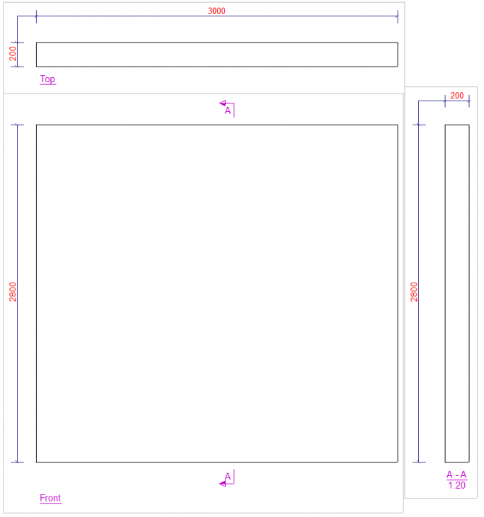
In case you want to define the alignment for view labels on drawing level, double-click in the drawing. Next click View creation (1) in the drawing properties and next select a view (2). Click the button View properties (3). A new dialog box appears. Go to the tab Label (4) to select an option for the alignment of the label (5):

1. Open a drawing and double-click on a view, dialog box View Properties appears.
2. Go to the tab Label and select an option in listbox Horizontal:
Image
The following example shows the option Left aligned to view restriction box for the view label:
Image
In case you want to define the alignment for view labels on drawing level, double-click in the drawing. Next click View creation (1) in the drawing properties and next select a view (2). Click the button View properties (3). A new dialog box appears. Go to the tab Label (4) to select an option for the alignment of the label (5):
Image
Align selected marks to a point
The Annotations tab in the drawing mode has a new command Align to a point for aligning selected marks around a point:

This new command tries to avoid crossing leader lines.
Suppose that you have a cast unit drawing from a beam including rebars in which the following marks are positioned:

Select the marks to be aligned, select the command Align to a point and pick a point:

Now position the marks:

If Ortho is on, the lines are placed in a 0, 90, 180, or 270 degree angle. You can also hold down the middle mouse button during the command to change the angle of the marks.

Image
This new command tries to avoid crossing leader lines.
Suppose that you have a cast unit drawing from a beam including rebars in which the following marks are positioned:
Image
Select the marks to be aligned, select the command Align to a point and pick a point:
Image
Now position the marks:
Image
If Ortho is on, the lines are placed in a 0, 90, 180, or 270 degree angle. You can also hold down the middle mouse button during the command to change the angle of the marks.
Image
Hatch pattern improved
In Tekla Structures 2019 hatch pattern ISO15W100 has been improved to create the correct pattern in drawings now:


Image
Image
Tools/plugins
Macro CS_Fill_IFC_ExportProps_With_Organiser_Values no longer available
Macro CS_Fill_IFC_ExportProps_With_Organiser_Values is no longer available in database Applications and components:

You could use this macro to write values from floors (ground floor, 1st floor and 2nd floor), defined in the Organizer, to the user-defined attributes on tab IFC export in the model object properties:

This is now done automatically in the Organizer and makes the macro superfluous.
Image
You could use this macro to write values from floors (ground floor, 1st floor and 2nd floor), defined in the Organizer, to the user-defined attributes on tab IFC export in the model object properties:
Image
This is now done automatically in the Organizer and makes the macro superfluous.
Part to part fitting (j003)
Tekla Structures includes plugin Part to part fitting (j003) for fitting and/or line cutting parts (concrete beams or walls, steel plates or beams) connecting to each other. The plugin has now been enhanced:

Image
BTL Export (ML019) - BVX Export (ML027) - Randek Export (ML077) - BVN Export (ML081)
Tekla Warehouse includes several export tools for generating production data for wood framing machines such as BTL Export (ML019), BVX Export (ML027), Randek Export (ML077) and BVN Export (ML081). These tools are updates frequently because of new functionalities or improvements or fixes:

Set an alert
You can set an alert in Tekla Warehouse for the tools to get informed automatically in case the content changes or if a new version is available:

Image
Set an alert
You can set an alert in Tekla Warehouse for the tools to get informed automatically in case the content changes or if a new version is available:
Image