Wall Elementation Components
Not version-specific
Tekla Structures
Environment
Not environment-specific
Wall Elementation Components
Contents
Purpose and description
System Requirements
Installing Wall Elementation Components
Using Wall Elementation Components
Additional information
1.Purpose and description
Wall elementation components are meant to be used to model prefabricated concrete wall structures, either solid walls, double walls or sandwich walls.
Elementation components is a set of seven plugin components which shall be used together:
- Wall manager
- Seam controller
- Edge controller
- Opening controller
- Detailing controller
- Corner handler
- Auto elementation
With wall manager plugin component you can model wall piece(s) over one region of the facade. Facade region is any planar area of the facade of the building containing walls having same thickness, material and other properties. Wall manager plugin also contains options to create polygonal line of facade regions by picking points at global XY-plane. However, it is good to notice that when using this “plan view” way of modeling the plug-in actually creates one or more individual facade regions to model. These individual facade regions can be further modified and managed separately.
The physical representation of planar region of the in Tekla Structures model is one (dummy) contour plate. You can get control over the shape of the facade region by modifying the shape of this contour plate. In this document we are referring to this (dummy) contour plate with the term “virtual facade part”
Wall pieces managed by wall manager can be split into two or more wall pieces by adding an instance of the seam controller plugin for the virtual facade part. The seam controller will split wall pieces into two. In addition to splitting the seam controller can also apply offsets to adjacent wall edges and/or apply a seam or connection between walls. Wall edges at exterior perimeter of the facade region can be detailed similarly by adding instances of edge controller plugins.
By adding instances of opening controller to the virtual facade part you can respectively apply opening components to final wall pieces.
Detailing controller plugin is a helper component that can be used to apply two or more detailing components with “one” click to walls created by wall manager and related components.
Corner handler will fit the corners by offsetting each layer. Corner handler can also be used with Edge controller attributes.
Auto elementation will add the horizontal and vertical seams together with the details, like reinforcement, lifting hooks etc. Basically, it’s using at the same time the Seam- and Detailing controller with their pre-set attributes. Seams are applied to the whole wall and divided by giving a maximum height and width for one element.
2. System requirements
n/a3. Installation
Run the installation and follow the instructions given on the screen.
4. Usage
4.1. Wall manager plug-in
Wall manager plug-in component is able to model one or more wall pieces ‘over’ the virtual facade part (=contour plate) and split the wall pieces into two or more when virtual facade part contains one or more seam controllers.
In addition to above core functionality wall manager component have also two alternative input case options. With help of these options it is possible to create a polygonal line of one or more virtual facade parts and at same time apply one wall manager component for each virtual facade part along the segments of the polyline
The wall pieces may be modelled using one the three different methods:
Each layer (1-n) is modelled using a beam part. The final shape will be achieved by adding line and/or polygon to the beam part
Each wall piece is modelled as an instance of custom part. Number of layers, materials etc are fully controlled by properties of the custom part, however (currently) the layer parts of the custom component will be detailed similarly as the beam parts.
Image

| Property | Description |
|---|---|
Creation | With this setting you can control which kind of input you want to give. Image
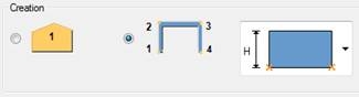
Please note that this property is valid only at the first time you insert the component, it can’t be modified after the wall manager component has been created. Please note that when 3rd option (“Pick facade part”) has been selected you need to have at least one contour plate in the model representing the planar region of the facade of the building. “Virtual facade part” is like a container or place holder for the one or multiple precast wall pieces. For other two options you can pick points (typically in global XY plane) and the plugin will create both the facade parts and the wall pieces for each segment (=facade part) of the polyline |
Facade height (H) | This property defines the default height of the “virtual facade part”. |
Wall creation | With this option you can control how the wall pieces are created. Please note that in order to get “Create walls as components” you need to have proper custom part available |
Layers | With this option you can control if the given layer will be created (=On) or not (=Off). When you select the third option “Void” there will be no actual layer created but there will be an empty space of given thickness between two other layers. |
Thickness | Thickness of the layer or the void |
Name | Name of the layer part |
Class | Class of the layer part |
Material | Material of the layer part |
Prefix | Prefix of the part numbering series of the layer part |
Start No. | Start number of the part numbering series of the layer part |
Image

Image

These properties can be defined only by selecting “Add new” from the Wall creation menu.
| Property | Description |
|---|---|
Name in dropdown | The name what is seen in the Wall creation menu |
Wall component name | Here you can select one of the predefined components or you can type the name of your custom part that will be used to create individual wall panels. Please note that this has to be available in the component catalogue, otherwise the creation of walls will fail. |
Component height 1 parameter name(s) | This input is set automatically and is not available for any of the predefined components. In case you are using your own custom part as the wall component this is the name of the wall height at wall start position. |
Component height 2 parameter name(s) | This input is set automatically and is not available for any of the predefined components. In case you are using your own custom part as the wall component this is the name of the property of the wall height at wall end position. If your component has only one height property (=constant height wall) leave this field empty. |
|
|
In following you can see some typical examples of the usage and output of the plugin
Facade input case = “Pick facade part”, (dummy) contour plate picked
Image

As an output one “big” wall piece is created. Please note that if the virtual faced part would have contained seam controllers there might be several wall pieces created at first stage already
Image

Facade input case = “Pick points for close wall line” (8 points picked)
Image

As an output 8 “virtual facade parts” along the line will be created and one wall manager plug-in is added for each of them causing the creation of the wall pieces.
Image

4.2.Seam controller plug-in
With seam controller you can split the wall pieces into two (or more) wall pieces. It is possible to give offsets for layers at the split location. Depending on your selection also the (custom) seam(s) between wall components or wall parts will be created.
Image

| Property | Description | ||
|---|---|---|---|
Seam modeling option |
| ||
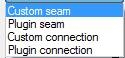
Seam component | With this setting you can control how the actual (custom) seam will be applied between two walls on both sides of this seam container. Following options are available. Image
 The meaning of the options are:
None – with this option only the offsets will be applied to wall edge and not any seam components will be created. Separate seams per layers – with this option you can input separate (custom) seam at each layer. Leaving the component name empty will not create any seam component. The input for the (custom) seam shall be one part. Same seam for all part’s layers – with this option you can input one seam component name. The input for the (custom) seam shall be all parts of one wall starting from first to last layer part. Same seam for component’s layers – with this option you can input one seam component name. The input for the (custom) seam shall be one custom part. Please note that this option shall be used only when the walls are created as components. | ||
Seam component name | Here you can select one the predefined seam components or you can type the name of your custom seam component to be inserted along the splitting line. When typing the name please make sure you have the custom seam in your component catalog. | ||
Seam component attribute file name | Name of the saved attribute file for given (custom) component. If no file name is given the ‘standard’ file will be used. | ||
Image
 | Here you can give the offsets (if any) at each layer on left/upper (a) or right/lower (b) side of the seam line. | ||
Direction |
Image
 Other direction options are relative to the edge direction.
|

As an input for the seam controller you should pick:
- “Virtual facade part” which is the original dummy part working as a container for wall pieces. You can also pick one of the wall pieces created by wall manager in which case the seam controller plug-in will find the correct virtual facade part automatically.
- Input points depending on the input case selection
Examples of usage of the seam controller
Vertical seam (one point)
Image

Horizontal seam (one point)
Image

Seam with two points (two points, seam & splitting restricted at seam ends)
Image

4.3. Opening controller plug-in
With help of opening controller you can add openings to final wall pieces. Wall manager is able to add opening components into correct wall pieces depending on the layout of the seams and location of opening controller instances.
Image

| Property | Description |
|---|---|
Opening component name | From this drop down list you can select any of the predefined opening components or you can type name of your custom component. This input specifies the name of the (final) opening component that will be added to wall piece at the location of the opening controller. For custom components and plugin components you need to give the name. You can also use some of the system components here, for system component please give the correct number. |
Component attribute file name | With this option you can specify the attributes used to insert the (final) opening component. If no name is given the ‘standard’ file will be used. |
Vertical offset | With this input you can specify the (global) vertical offset for the opening components input point. This is practical for example in a case where you are working in the plan view and want to give the elevation offset of the window from the view plane. |
Opening component input case | Image

With this option you need to specify what type of input will be used to insert the (final) opening component. Please make sure you have correct input case which is compatible with the selected component name/number. |
As an input for the opening controller you should pick:
- “Virtual facade part” which is the original dummy part working as a container for wall pieces. You can also pick one of the wall pieces created by wall manager in which case the seam controller plug-in will find the correct virtual facade part automatically.
- One point which will be used as the first input point for the (final) opening component.
Example of the opening controller
Image

4.4. Edge controller plug-in
With edge controller you can apply offsets and/or seam components to exterior edges of walls in the facade segment.
Image

| Property | Description | ||||||
|---|---|---|---|---|---|---|---|
Edge modelling option | With this setting you can control how the edge location, length and direction are defined. Please note that normally the edge controller shall be parallel to existing exterior edges but in some cases this is not necessary.
| ||||||
Seam component | With this setting you can control if the seam components will be applied at edge. Following options are available. Image
 The meaning of the options are:
None – with this option only the offsets will be applied to wall edge and not any seam components will be created. Separate seams per layers – with this option you can input separate (custom) seam at each layer. Leaving the component name empty will not create any seam component. The input for the (custom) seam shall be one part. Same seam for all part’s layers – with this option you can input one seam component name. The input for the (custom) seam shall be all parts of one wall starting from first to last layer part. · Same seam for component’s layers – with this option you can input one seam component name. The input for the (custom) seam shall be one custom part. Please note that this option shall be used only when the walls are created as components. | ||||||
Seam component name | Here you can select one the predefined seam components or you can type the name of your custom seam component to be inserted along the edge. When typing the name please make sure you have the custom seam in your component catalog. | ||||||
Seam component attribute file name | Name of the saved attribute file for given (custom) component. If no file name is given the ‘standard’ file will be used. | ||||||
Component type | Edge controller is able to create many types of components. With this option you shall specify the type of the component. The supported component types are: Image
 | ||||||
Direction | With this option you can control the up direction of the applied component. Up direction is given in the facade local coordinate system where ‘Front’ and ‘Back’ are perpendicular to facade and ‘Front’ is pointing “out” from the first layer. Other direction options are relative to the edge direction. Image

| ||||||
Image
 | Here you can give the offsets (if any) at each layer at the edge.
Please note that offset values are used only when the edge controller is parallel to original edge of the wall. If the edge controller is not parallel to original edge you can still apply the seam component and depending on the component it may still apply some offsets. | ||||||
|
|


As an input for the edge controller you shall pick:
- “Virtual facade part” which is the original dummy part working as a container for wall pieces. You can also pick one of the wall pieces created by wall manager in which case the edge controller plug-in will find the correct virtual facade part automatically.
- One or two points depending on the edge modelling option.
Examples of usage of the edge controller
Image

4.5. Detailing controller
Detailing controller is a helper component which can be used to apply typical detailing components into a wall created with or without wall manager. With help of detailing manager you can apply up to eight detailing components with “one click” to a wall.
Image

With these properties you can control which additional detailing components will be added to wall. These are typically component to create lifting loop and/or reinforcement i.e. components where the input is single part or component.
| Property | Description |
|---|---|
Component name | Here you can select any of the predefined components from the drop down list or you can type the name or number of the detailing component. This can be name of any custom component (or a number of any system component) accepting only one component or part as its input. |
Component attribute file name | Name of the saved attribute file for given component. If no file name is given the ‘standard’ file will be used. |
Component input | With this option you can select into which layer part of the wall the detailing component will be applied. The first option ‘Component’ shall be selected only when the walls are created as custom parts and the given detailing component is accepting custom part as it’s input. |
Example of Detailing controller
Image

4.6 Corner Handler
Corner handler will fit the corners by offsetting each layer. Corner handler can also be used with Edge controller attributes. To insert edge controllers to walls, pick a virtual part 1 and 2.
Image

| Property | Description |
|---|---|
|
|
| Here you can set the gap between two layers |
Edge controller attributes 1&2 | Here it’s possible to apply the same attributes which are defined in Edge Controller. |


Example of the Corner handler
Image

4.7 Auto elementation
Auto elementation will add the horizontal and vertical seams together with the details, like reinforcement, lifting hooks etc. Basically, it’s using at the same time the Seam- and Detailing controller with their pre-set attributes. Seams are applied to the whole wall and divided by giving a maximum height and width for one element.
Image

5. Additional information
5.1. Wall manager (automatic) update limitations
Currently wall manger is automatically updated only when the seam controller is created or modified.
However, you can make the updating by double clicking wall manager plug-in instance and click the modify button in the plug-in dialog.