Half Slab Reinforcement
Not version-specific
Tekla Structures
Environment
Not environment-specific
Versatile tool for detailing braced girders and reinforcement to half-slabs.
Back to topInstalling Half Slab Reinforcement
To install the extension:
- Download from Tekla Warehouse
- Run downloaded .tsep file
- Run Tekla Structures
Objects Created
- Single Rebar
- Rebar Group
- Brace Girders
Use for
| Situation | Description |
|---|---|
|
Image
 Image
 |
Reinforcement with rebars, extended rebars or brace girders. |
To use the extension:
- Create a beam or slab objects
- Select a concrete beam or slab
The reinforcement is created automatically based on the parameters you chose.
Reinforcement
Creates reinforcement in selected concrete part.
It has three main settings:
| Option | |
|---|---|
|
Image
 |
Manual single zone |
|
Image
 |
Manual multiple zones |
|
Image
 |
By reinforcement areas |
Manual single zone
| Option | Description |
|---|---|
|
Image
 |
Reinforcement = Manual single zone. Here you choose if you want to manage your reinforced area as a single zone, multiple zones or by reinforcement areas. |
|
Image
 |
Reinforcement = Reinforcement area. Here you choose if you want to calculate the reinforcement area in centimeters squared, millimeters squared or by spacing. If you choose the first two options, the number in the first text box is the minimal possible density of rebars to meter squared. And if you choose Spacing, this number will be taken as a distance between rebars. The fix diam textbox indicates the size of rebars. |
|
Image
 |
Reinforcement = Create on selected objects. Here you can apply reinforcement to all selected objects that pass your filter. |
Manual multiple zones
Here you can split reinforced area up to five zones and manage each individually.| Option | Description |
|---|---|
|
Image
 |
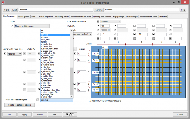
Reinforcement = Manual multiple zones. Here you choose if you want to manage your reinforced area as a single zone, multiple zones or by reinforcement areas. |
|
Image
 |
Reinforcement = Reinforcement areas. Here you choose if you want to calculate the reinforcement area in centimeters squared, millimeters squared or by spacing. If you choose the first two options, the number in the first text box is the minimal possible density of rebars to meter squared. And if you choose Spacing, this number will be taken as a distance between rebars. The fix diam textbox indicates the size of rebars. |
|
Image
 |
Reinforcement = Zones size. Here you decide if you want to split the zones either by percentage or by real distance. According to your decision, the unwanted row will be grayed out. |
|
Image
 |
Reinforcement = Create on selected objects. Here you can apply reinforcement to all selected objects that pass your filter. |
By reinforcement areas
| Option | Description |
|---|---|
|
Image
 |
Reinforcement = By reinforcement areas. |
Brace Girders
Creates brace girders on your selected concrete part.
| Option | Description |
|---|---|
|
Image
 |
Braced girder type = Choose type. Creates brace girders based on the type you have selected. |
|
Image
 |
Braced girder type = Choose group and type. Creates brace girders based on the group and type you have selected. Group and type are taken from the excel file you have imported. |
|
Image
 |
Braced girder type = Based on floor thickness. Correct braced girder is selected from the imported excel list. It will use the maximum girder height that does not clash with the reinforcement in the CIP topping |
|
Image
 |
Braced girders = Spacing. You can define the spacing between brace girders. Either as maximal spacing, exact spacing from right to left, exact spacing from right to left, exact spacing auto, grid from right to left, grid from left to right, grid auto. You can define space between the edge of your part and first and last brace girder on top bottom and on sides. You can also define space between the first two and last two brace girders. |
|
Image
 |
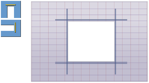
If there is a hole or embed in your part you can define extra girders around. Embed is found by the filter you selected. |
|
Image
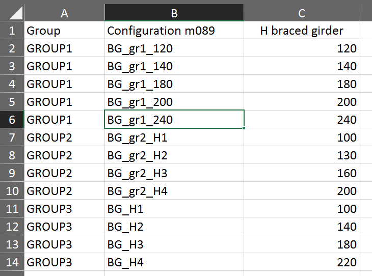 |
Example of excel file used for brace girders. |
Grid
Manages reinforcements positions.
| Option | Description |
|---|---|
|
Image
|
To have this tab visible you must first select YES in the Extended user-interface comboBox in the Attributes tab. |
|
Image
 |
Grid = Position. Here you manage the position of your rebars. You can choose from five options. Such as Free which creates rebars freely, with no respect for the Grid. Grid each position creates rebars one each grid line. Grid free position creates rebars not on every grid line. Grid max one neighbor creates rebars on the grid with only one rebar next to it. And No rebars obviously creates nothing. |
|
Image
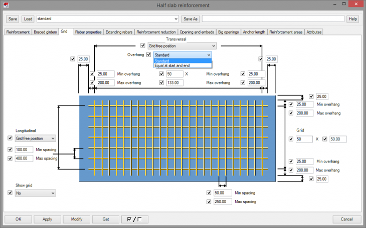 |
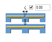
Grid = Overhang. You can define the define minimal and maximal overhang on both sides of your rebars for transversal as for longitudinal. You can choose between standard settings, which will create an overhang on the start and on the end separately. Or you can choose Equal at the start and end settings. This will create Overhang same on both sides. You can also define how further from the parts edge you want your rebars to start. |
|
Image
 |
In the first text box, you define the number of rebars in the grid. And in the second textbox, you define the minimal distance between rebars. |
|
Image
 |
You can also define the minimal and maximal spacing between rebars. For transversal as for longitudinal. |
|
Image
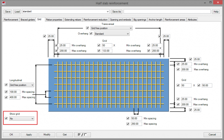 |
If you want you can show the grid. |
Rebar Properties
| Option | Description |
|---|---|
|
Image
|
To have this tab visible you must first select YES in the Extended user-interface comboBox in the Attributes tab. |
|
Image
 |
Defines some rebar properties. |
|
Image
 |
Possibilities for creating rebars. |
|
Image
 |
Connects rebars that are closer to each other than this defined distance. |
|
Image
 |
Longitudinal direction defines the direction of longitudinal rebars. You can use slab X or Y direction or use the global X and Y direction. |
|
Image
 |
You can define more than one diameter and they will be all taken into consideration. Unless you define the Maximal number of consecutive diameters. Then it takes n diameters that fit the best into the part. If Rebar length is not fulfilled, default values will be used. The same goes for the Minimum number of welding points. Default values for Rebar length are from 200 to 100000. The default value for the Minimum number of welding points is 2. If at least two welding points are not found, the rebar will not create. If Create only extended rebars is set to "YES", then only rebars set on tab page Extending Rebars will be created. |
Extending Rebars
| Option | Description |
|---|---|
|
Image
 |
Defines extended rebars. |
|
Image
 |
You can choose if you want to extend your current rebars or create new extended rebars for start and end. |
|
Image
 |
You can decide if you want to extend rebars through the cut side of your concrete part or not for start and end. |
|
Image
 |
You can define the shape of extended rebar for start and end. You can also define the diameter, number of extended rebars and spacing. |
|
Image
|
You can choose if you want to create n rebars from both sides of from right to left or from left to right. |
|
Image
 |
You can also create extended rebars for the top and bottom side of your created concrete part. You can also define the angle, radius, and length of the hook. |
Reinforcement Reduction
Reduces the length of some rebars.
| Option | Description |
|---|---|
|
Image
 |
Reinforcement reduction = Single zone. Reduces the length of some rebars. But the minimal and maximal spacing set up on Grid tab must be respected. So the reducing must not violate that. If it does, it will not happen. |
|
Image
 |
Reinforcement reduction = multiple zones. Reduces the length of some rebars for each zone separately. But the minimal and maximal spacing set up on Grid tab must be respected. So the reducing must not violate that. If it does, it will not happen. |
|
Image
 |
Reinforcement reduction = multiple zones with advanced options. Reduces the length of some rebars for each zone separately. Also, you can separately manage how you want to reduce every zone. But the minimal and maximal spacing set up on Grid tab must be respected. So the reducing must not violate that. If it does, it will not happen. |
|
Image
 |
Possibilities for reduction. |
|
Image
 |
When managing multiple zones you can in advanced mode choose one of these possibilities for each zone. |
Openings And Embeds
| Option | Description |
|---|---|
|
Image
 |
Here you define openings and Embeds. You can define how far from opening or embed rebars should create. Also, define some parameters for extra rebars. You can decide not to cut rebars if the total selection of cut rebars in bigger than yours defined number. |
|
Image
 |
You can define embed by a filter. You can decide if you want your rebars cut if they are above or under embed. Or you can define the distance rebar to ember to which they will be cut. |
|
Image
 |
You can define if you want to create extra rebars for opening or embed bigger than the defined number. You can, for example, define rebar diameter or anchor length. |
Big Openings
| Option | Description |
|---|---|
|
Image
 |
Here you define extra rebars for big openings. You can define how big opening should be considered, you can choose a number of extra rebars and their diameters. You can define a distance of extra rebars from opening and between one another. Or you can allow creating of loose rebar, which means that when you have snapped rebars to the grid, the extra rebar may not fit the grid, so this allows the extra rebar to create outside the grid. |
|
Image
 Image
 |
You can create extra rebars that extend beyond the hole just by a certain distance, which you define in the Anchor length tab. Or you can create extra rebars that extend beyond the hole to the edges of the concrete part. |
Anchor Length
| Option | Description |
|---|---|
|
Image
 |
Anchor Length = Way of calculation. Here you define the anchor length, either by formula or by excel file. |
|
Image
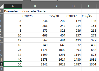 |
Example of excel file used for anchor length. |
Reinforcement Areas
| Option | Description |
|---|---|
|
Image
 |
Here you can define areas that you want to reinforce by creating another part above or below your existing one. Class and Name must be the same as your new part. You can set limitation in Z-axis either by distance or by level. Information containing the number of mm2 reinforcement in longitudinal and transversal direction is stored in the new parts UDA. The attribute name, which contains the needed information is written in the last two textboxes. Do not forget to switch to By reinforcement areas in Reinforcement tab. |
|
Image
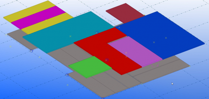 |
A plate in the model can only be considered as a Reinforcement area if: - the class belongs to the Class list - the name belongs to the Name list - the height above or below the input filigree-plate is between the bottom and top level limit. In case, reinforcement areas are overlapping, we consider the one with the maximum reinforcement-value. But the result of which reinforcement area will be considered in which area can be different for the longitudinal and the transversal reinforcement. |
Attributes
| Option | Description |
|---|---|
|
Image
 |
You can define some attributes for your rebars. Such as Name - the name of the rebars Class - class of the rebars Grade - grade of the rebars. |
|
Image
 |
By Extended User-interface you add or remove two tabs, Grid and Rebar properties. |
Back to top