Drawing Symbol Manager
Not version-specific
Tekla Structures
Environment
Not environment-specific
Note: Since Tekla Structures 2016, this extension is included in the installation as 2D Library.
Image
1. Purpose and description
This tool allows you to easily select objects in any drawing and save them away as a 2D drawing detail. The details can then be inserted in other views and drawings in any model.
2. System requirements
Tekla Structures configuration: Any
Environments: Any
3. Installation and launch
To install and launch the extension:
- Download and launch the appropriate 32bit or 64bit (x64) Drawing Symbol Manager installer. The installer will automatically detect your environment and install toolbars and files to the appropriate folders.
- Restart Tekla Structures, open a model and then a drawing. A new toolbar with an icon should appear in the user interface.
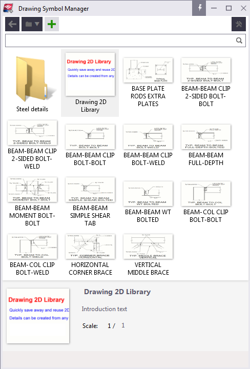
4. Basic Usage
Open a drawing and launch the tool. You are presented with the user interface which contains a list of available details.
4.1. Detail folders
The folder drop-down menu lets you switch between the Current model, Project, Firm and System folder. In each of these, the tool searches for and displays details from the subfolder 'Drawing Details'. Any other folder can be used with the 'Browse' command in the menu.
The Project and Firm folders are available if XS_PROJECT and XS_FIRM are defined respectively. The System folder displays details found in any of the XS_SYSTEM folders.
Any subfolders are shown next to the details in the detail list. Double-click a folder to view the details within it.
In the Current model folder, you can create a new subfolder by clicking the ‘New folder’ command in the folder menu. The folder can be renamed by selecting it and editing its name in the info bar.
4.2. Insert a detail
- Click the detail in the detail list
- Pick a point in the drawing to insert the detail
The detail is inserted and scaled according to the target view. A new view is created if the detail is inserted outside of any view (this behaviour can be changed from the settings menu).
A detail is inserted as a plugin, which means that the detail objects are grouped and stay together when you select or move them in the drawing.
If a detail is inserted from any other folder than the Current model folder, it will automatically be copied to the Current model folder (if it's not found there already) and referenced from there. This is to ensure that all the details are available when sharing the model.
4.3. Create a new detail
Note: You can only create new details in the Current model folder (or one of its subfolders). You can change the folder from the folder drop-down menu in the UI.
To create a new detail,
- Select the objects in the drawing that will make up the detail
- Click the ‘+’ icon in the Drawing Symbol Manager
- Pick a reference point in the drawing
- Capture a preview image by picking two points
The detail is saved to disk and will show up in the detail list.
4.4. Get details to Project, Firm and System folders
To copy or move a detail to any folder other than the Current model folder, use the Windows file explorer. Copy both the .ddf and the .png files. Remember that in Project, Firm and System folders the target folder should be a subfolder called 'Drawing Details'. Create this folder if it's missing.
The reason for this limitation is to prevent the end user from editing the content of the Firm, Project or Environment folders without considering the impact it might have.
4.5. Edit a detail
Note: You can only edit details in the Current model folder (or one of its subfolders).
After selecting a detail in the list, you can edit the detail name, description and scale directly in the info bar below the detail list.
The scale refers to the scale of the view that the detail was originally created from. This value is used when inserting the detail to adapt the detail to the scale of the target view.
To prevent this visual re-sizing, click ‘Ignore scale’ or change the scale to 1/0. This value means that regardless of the target view, the detail will always be inserted with the same visual size. However, keep in mind that this will make dimensioning output wrong results.
To change the preview image you can right-click the detail in the list and select ‘Capture new image’. This lets you pick two points to capture a new image.
To update the detail objects, you first select the new set of objects in the drawing, then right-click the detail in the detail list and click ‘Update detail with selected objects’. The tool asks you to pick a new reference point. If you’re updating the detail in the same view that it was originally created in, you can interrupt the picker to re-use the old reference point.
When you’re updating a detail with new objects, any inserted detail in any drawing will be updated as well.
4.6. Copy and move details and folders
Note: Through the UI, you can only cut or paste details in the Current model folder (or one of its subfolders). Details can be copied from another location though.
Details and folders can be cut or copied by right clicking the detail and clicking ‘Cut’ or ‘Copy’. They can then be pasted into another folder by navigating to that folder, right-clicking the detail list and clicking ‘Paste’. If you right-click a subfolder that is visible in the detail list and click ‘Paste’, the detail will be pasted into that folder instead.
Ctrl+X, Ctrl+C and Ctrl+V can be used as shortcuts for cut, copy and paste.
4.7. Options
If you click the options symbol in the top right corner you’ll find a few additional settings.
Explode native symbols
Per default the tool saves ordinary drawing symbols as symbols, which means that later when you insert the detail you need to have the correct symbol files present. With this option checked the tool will explode ordinary drawing symbols into their constituent graphical elements, thus making them independent of the local symbol files.
Exclude hatching
Use this option to avoid capturing hatches.
Create view if needed
With this option enabled, if a detail is inserted outside of any view, a new view will be created. The new view will use the currently applied view settings and gets the same scale as the detail.
Note that if details are inserted without a view, dimensioning will not work properly on them.
5. Known limitations
There are certain API limitation that restrict the capabilities of this tool. For example:
- Multi-colored part section hatches cannot be captured, instead the part face hatch will be used.
- Manually added weld marks cannot be captured. This is also the case for certain other marks, e.g. revision mark, level mark.
- Templates cannot be captured.
- Hatches can sometimes hide the borders of a part/shape when a detail is inserted. If hatches aren't necessary, you can use the option 'Exclude hatches' to avoid this problem.
- Inserted details don't rotate if the view is rotated.
- Inserted details can't be cloned.
- In 21.0, custom line types won't be captured. A solid line will be used instead. Furthermore in 21.0, the hatch color 'Special' (which might be the same as 'Automatic') will become black.
If the detail doesn’t look right on insert, it’s possible to right-click it in the drawing and click ‘Explode’. This allows you to edit the detail objects. The drawback is that the objects aren’t grouped anymore, nor recognized as a drawing detail. In some cases, after modifications, you can select the modified objects and update or create a new detail to capture the correct appearence.