Combine Part Marks
Not version-specific
Tekla Structures
Environment
United States (Imperial)
United States (Metric)
Back to top
 Back to top
 Back to top
Purpose and description
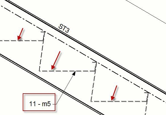
This tool allows users to create a combined part mark callout for parts on assembly drawings where the out of the box combine part marks doesn’t achieve the desired result. The user selects a part in the assembly drawing and the tool will automatically scan through the view the part was selected in and it will find the quantity of parts with the same part mark that appear in that view. The user then picks to points which represent the location of the mark leader and then the placement point of the mark text. The part mark content will then display the quantity of that part mark found in the view (not the entire drawing), then “-“, and ends with the part mark itself.
Image
System requirements
Environments: Default, Usimp, Usmet
Languages: English
Installing Combine Part Marks
To install the application:
- Have Tekla Structures closed during installation.
- Install the appropriate installation package that you can download from the Tekla Warehouse. (Before 2016i install the .msi. 2016i and newer install the .tsep.)
- Reopen Tekla Structures once installation is complete.
- Before version 2016: A new toolbar icon which will launch the tool should now be visible when a drawing is opened. For version 2016 a new thumbnail under Ungrouped items in the Applications and components side pane will appear. For version 2016i and newer a new thumbnail under US Extensions items in the Applications and components side pane will appear.
Note: In the .tsep installation, there will be a large (CombinePartMarks32x32.png) and small (CombinePartMarks16x16.png) icon installed that can be used to add this tool to the ribbon in v2016i and newer. Once the .tsep is installed, the 2 images will be placed here: ..TeklaStructures\2016i\Extensions\Images. Browse to this location in the Customize Ribbons dialog box to add one of these icons to the desired place in the ribbon.
Before v2016:
 v2016+:

Back to top
Image
Image
Using Combine Part Marks
To use the application:
- Open an assembly drawing where you would like to combine part marks.
- Start the tool from the provided icon/thumbnail that has been added. This is not a macro but a drawing plugin so it can’t be started from the tools>macros dialog box.
- You will then be prompted to pick a part in the drawing in order to figure out which part mark to find the quantity of and create the combined part mark.
- Then pick the point locating the head of the leader line, and then a point to place the location of the text of the combined part mark.
- The user can drag the part mark, or select either of the two input points and change the position of the part mark after it has been inserted on the drawing.
- The representation of the part mark and leader is controlled through the drawing text properties. The user can open the text properties dialog box and set color, linetype, frame, etc then save away those settings with a name. The user can then open up the Combine Part Mark properties dialog box and type the name they save in the text properties dialog box, then modify existing combined part marks, or press Apply, to apply those settings for new combined part marks that will be added to the drawing. The tool doesn’t read the settings from the part marks property dialog box, just the text properties dialog box.
- The combined part mark is parametric and will update the quantity and mark if the model has changed and the drawing is reopened. The mark may disappear if the original ID/part instance that you selected to associate the combined part mark to in the drawing has been deleted from the model.
- Mark Format String. The user can add custom text data to the mark in the Mark Format String text box. For example if the user wanted to see the format p23 (16 PLC’S) they could type MARK (QTY PLC’S) in the Mark Format String textbox. The word MARK (all capital letters) and QTY are special codes for the tool to intelligently replace with the calculated Mark and Quantity values. They are English specific only. If you leave the field blank it will default to QTY-MARK.
Image
Additional information
- The tool doesn’t replace parts marks altogether but is more meant to be a supplemental tool where the out of the box combine part marks doesn’t provide the desired results.
- The tool is primarily meant for shop drawing and only scans the part mark (part position) property on parts to create this combined part label.
- Only the quantity and part mark (part position) property are displayed in the mark. No other properties about the part can be displayed in the combined mark.
- The tool does not automatically delete out existing drawing part marks. The user must manually delete part marks that are not desired to be on the drawing.
- If the original part ID or instance is deleted from the model that the part mark was associated to on the drawing, then the part mark plugin will be deleted from the drawing.