Creating a report
Not version-specific
Tekla Structures
Environment
Not environment-specific
A step-by-step guide to creating a basic report from scratch
#Creating new report#Adding a header
#Adding value fields
#Testing report
#Adding a row
#Adding value fields to row
#Cropping row
#Moving row down a level
#Summing value fields
#Adjust row height
#Adding a footer
#Adding a footer
#Adding weight and area
#Adding bevel field and rule
#Adding separating lines
Creating a report (textual)
Open the template editor from Tekla in DRAWINGS & REPORTS
Create a new Report by selecting FILE -NEW and then TEXTUAL
Create a header using INSERT and the top then COMPONENT and then HEADER
This should add you a red rectangle as shown below
The background of the Template editor is white as default, to change this to grey as below go to OPTIONS - PREFERENCES - WORKAREA and change the background color to grey.
Image

We are now going to enter the text below into the header, to do this you must click on INSERT then TEXT and type into the box what you wish to show. This can then be placed inside the header.
Add the following header information:
- Material list
- Company Name
- Project No.
- Project Title
Image

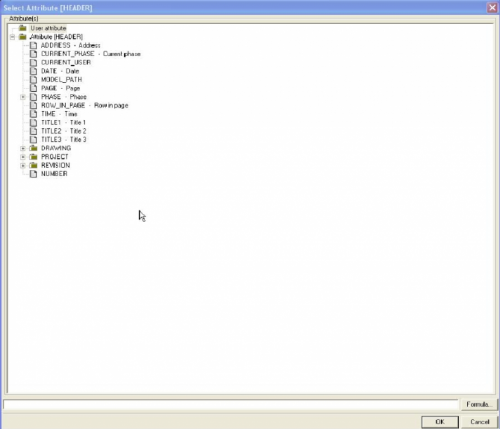
We are then going to add two value fields, one next to Project No. and one next to Project Title.
Value fields are there to pull information from the model and insert it into the report.
To add a value field we need to press on the abc button at the top with the white background. This will then
allow us to click inside the page header and the following box will appear. We are going to add Project No and
Project Title, we will need to drop down the folder called PROJECT from the list below and select Project
number, we are selecting the project folder because the project number and project title will come from
PROJECT PROPERTIES within Tekla.
Image
Once the Value fields have been added the report should now look like this. You can increase the number of characters on the value fields by double clicking them and changing the length.
For the project title value field you will need to copy the project number one down, double click on it, go to ATTRIBUTE at the top and select Name.
Image

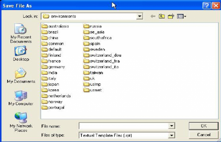
Save the Report - When you go to FILE and SAVE you will be presented with the following box. Double click on
the uk folder and then double click on the template folder. You will then need to give your report a name in the
file name box to the left of OK. Enter the desired name and press ok.
Image
You should now be able to see your report in the report list Tekla.
Run the report in Tekla and make sure it looks something like this:
Image

Go back into the template editor, the next step is adding a blank row and entering some text in.
To add a row go to INSERT at the top and then COMPONENT and then ROW, leave the content type blank because all we are entering in this is text. When you click on ok it should appear like this:
Image

We can now enter the text into the row, to make it easier you can enter one piece of text and then select it and copy it, then modify it to suite. When the text has been entered it will look like this:
Image

Again, once the text has been entered save the report and run it again in the model to check that the text has appeared and it is in the correct place. The report should look like this:
Image

The next stage is adding another row. This time it will be used to pull information from the model relevant to the
text we entered. We do this using the value field again - exactly the same process as the PROJECT NO and
PROJECT TITLE - only this time we will be using values relevant to the members in the model.
Again, to add a row go to INSERT - COMPONENT - ROW and this time choose ASSEMBLY. Click ok and it will enter the row in for you as shown below.
Image

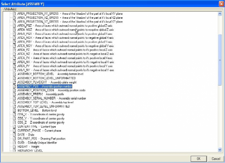
We are now going to enter the value fields under the relevant text in the assembly row. We are only interested in putting value fields in for MARK
and QUANTITY.
To enter the value fields we need to click on the white ABC button at the top, or you can copy one of the fields down from
PROJECT NUMBER/PROJECT TITLE. Once you have done this double click on the field itself and go to attribute at the top. Under the top
folder called Attribute [ASSEMBLY] we need to choose the relevant field for MARK. This is called ASSEMBLY_POS as shown below
Image
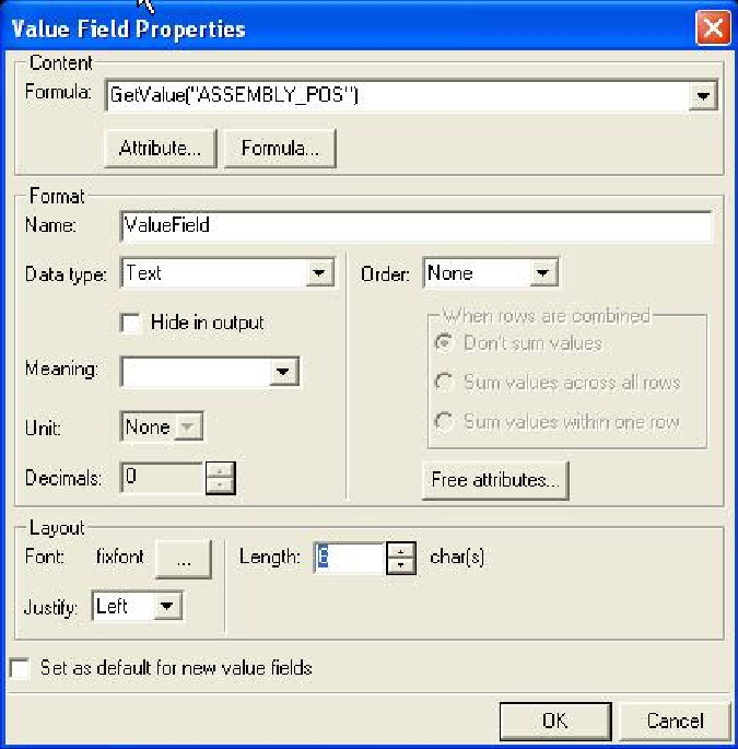
When this value field is inserted it can be tweaked on the number of characters it contains. For Assembly mark
this would probably be no more than 6 but adjustments can be made after if necessary. The length is shown below highlighted in blue.
Image
Once the value field for the assembly mark is inserted it can then be copied and pasted under quantity. Again double click in the value field we have just pasted and change the attribute to QUANTITY.
Image
Once this is done, save the report and run it in the model. The results should be as shown below.
Image

To make the gap smaller between Mark and the actual mark the report produces we will need to CROP the row in our report. To do this select the first
row we put in and right click, select CROP and then COMPONENT HEIGHT. Do this for the second row also. Save the report again and run it in Tekla
to view the changes as shown below compared to the above picture.
Image

For the rest of the fields i.e. Mark, Quantity, Profile, Length, Weight etc. we will need to add another row but the
row type this time will be PART. The reason for this is so that we can get the individual lengths weights and
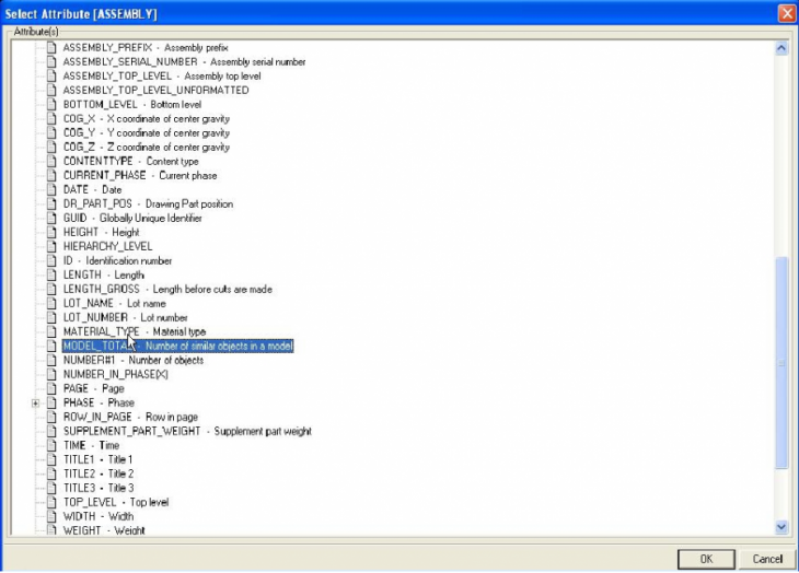
areas of each part. Again as explained above, add the value fields under the relevant text MARK - QUANTITY -
PROFILE - LENGTH - WEIGHT - AREA and select the relevant attribute for each one. If asked to load the
default setting for each attribute please select YES, this will then change the data type and meaning etc.
- Mark = PART_POS
- Quantity = MODEL_TOTAL
- Profile = PROFILE Length = LENGTH
- Weight = WEIGHT_NET
- Area = AREA
Once these have been added in we will need to make the PART row a sub-row to the ASSEMBLY row. To do
this select the part row in the box on the left as shown below and then choose the SHIFT ROW DOWN A
LEVEL button at the top

STEP 1 - select the PART ROW
STEP 2 - select the SHIFT ROW DOWN A LEVEL button
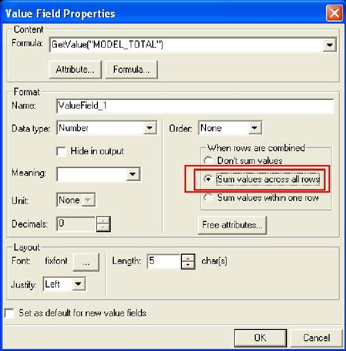
To make sure that all the parts are included in this report we will need to make sure that the quantity field sums up all of the parts in the model.
To do this double click on the value field for quantity and then select Sum values across all rows.
To get the spacing correct between the different lines we will need to adjust the height of our rows. As you can
see below the first and second rows on my report have been made one line higher, to do this select the row and
then drag the handle that is visible in the middle of it up one. I Have shown the space with arrows below, and
also a picture of the handle highlighted.


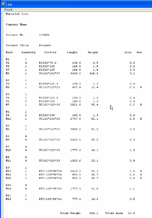
Save the report again and run it in the model. If your model has a few connected pieces it should display like this:

The next and final stage of the report is adding a page footer with the Total weight and Total area in. To add a page footer go to
INSERT - COMPONENT - PAGE FOOTER you should then see a green box appear below the rows. You will then need to
add text under the relevant colums as shown below. I have purposely left gaps so that the value field can be placed in underneath the relevant columns.

We then need to tell the report to add up the weight and area. To do this we use a different command in the attribute. Firstly copy the weight value field
down and place it next to the total weight text. Do the same for area.

For the next stage you will need to double click on the WEIGHT value field and look at the name under format. You will need to highlight this and right click and copy.

For the next stage double click on the TOTAL WEIGHT value field and go into formula and delete anything under formula. You will then need to drop down the box under
Value Field and select Sum, then paste the copied name of the weight value field between then commas as shown.

The same process can be used for the area, the only difference being that you will need to copy the areas name instead of the weights because that is the one you want to sum up.
This is how the totals should look:

The final stage of the report will be adding the Bevel field on, this shown as a B on the report next to any member that is beveled.
The first thing to do is add some text in the top row saying Bevel or Bev depending on how much space you have left.

You’ll need to copy a value field, change the length of the characters to 1 and move it under the Bev column.
Double click on the value field and go into formula. The following formula will need to be pasted into the box:
if GetValue("END1_SKEW")== 1 || GetValue("END2_SKEW")== 1 then "B"
else
""
endif
This is telling the report to add a B to the column as long as either ends are skewed.
Save the report and run it on a beveled member in the model. It should display as shown below.
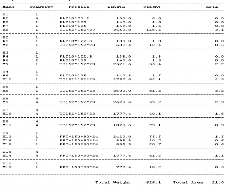
For cosmetic purposes you can add lines to the report to split the separate section up, these can be put in as text using the dash key as shown where the red boxes are.

This makes the report appear as so:
Image
STEP 1 - select the PART ROW
STEP 2 - select the SHIFT ROW DOWN A LEVEL button
To make sure that all the parts are included in this report we will need to make sure that the quantity field sums up all of the parts in the model.
To do this double click on the value field for quantity and then select Sum values across all rows.
Image
To get the spacing correct between the different lines we will need to adjust the height of our rows. As you can
see below the first and second rows on my report have been made one line higher, to do this select the row and
then drag the handle that is visible in the middle of it up one. I Have shown the space with arrows below, and
also a picture of the handle highlighted.
Image
Image
Save the report again and run it in the model. If your model has a few connected pieces it should display like this:
Image
The next and final stage of the report is adding a page footer with the Total weight and Total area in. To add a page footer go to
INSERT - COMPONENT - PAGE FOOTER you should then see a green box appear below the rows. You will then need to
add text under the relevant colums as shown below. I have purposely left gaps so that the value field can be placed in underneath the relevant columns.
Image
We then need to tell the report to add up the weight and area. To do this we use a different command in the attribute. Firstly copy the weight value field
down and place it next to the total weight text. Do the same for area.
Image
For the next stage you will need to double click on the WEIGHT value field and look at the name under format. You will need to highlight this and right click and copy.
Image
For the next stage double click on the TOTAL WEIGHT value field and go into formula and delete anything under formula. You will then need to drop down the box under
Value Field and select Sum, then paste the copied name of the weight value field between then commas as shown.
Image
The same process can be used for the area, the only difference being that you will need to copy the areas name instead of the weights because that is the one you want to sum up.
This is how the totals should look:
Image
The final stage of the report will be adding the Bevel field on, this shown as a B on the report next to any member that is beveled.
The first thing to do is add some text in the top row saying Bevel or Bev depending on how much space you have left.
Image
You’ll need to copy a value field, change the length of the characters to 1 and move it under the Bev column.
Double click on the value field and go into formula. The following formula will need to be pasted into the box:
if GetValue("END1_SKEW")== 1 || GetValue("END2_SKEW")== 1 then "B"
else
""
endif
This is telling the report to add a B to the column as long as either ends are skewed.
Save the report and run it on a beveled member in the model. It should display as shown below.
Image
For cosmetic purposes you can add lines to the report to split the separate section up, these can be put in as text using the dash key as shown where the red boxes are.
Image
This makes the report appear as so:
Image