Create a concrete lofted slab
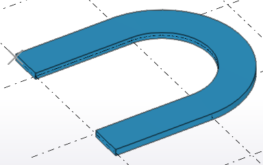
With lofted slabs you can create curved and double-curved slabs or walls, for example.
Prerequisites and examples of lofted slabs
Before you can create lofted slabs, you need to have construction objects in your model. Tekla Structures creates the shape of the lofted slab according to the geometry of the used construction objects, by connecting the start point of the first construction object to the start point of the second construction object. The end points of construction objects are connected in similar way.
You can connect the following construction objects as a lofted slab:
-
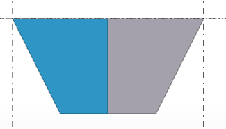
construction line to construction line
For example:
-
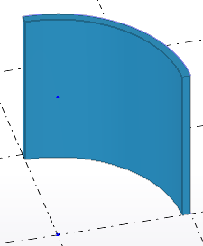
construction line to construction arc
For example:
-
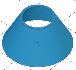
construction arc to construction arc
For example:
-
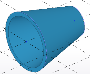
construction circle to construction circle
For example:
-
construction polycurve to construction polycurve
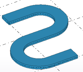
Note that rebar sets do not work with lofted slabs.
Create a lofted slab
-
Create the needed
construction objects in the model. The shape of the lofted slab is based on
the construction objects' shape.
You need to have
-
or
-
With polycurves, use the Create arc by tangent or Create tangent line options
 on the
construction polycurve toolbar. To create polycurves only with
straight segments, use the Create line
option
on the
construction polycurve toolbar. To create polycurves only with
straight segments, use the Create line
option  . Note that the construction polycurves do not need to have
the same number of segments, as long as both of them are
tangential.
. Note that the construction polycurves do not need to have
the same number of segments, as long as both of them are
tangential.
-
On the toolbar that appears,
click a button to specify whether to create the lofted slab by using two
construction objects, or by using a construction object and a point.
-
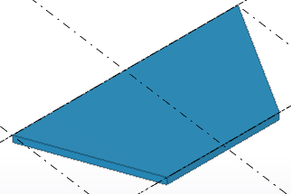
Use two construction objects
 to create a
lofted slab:
to create a
lofted slab:-
Select the first construction object: line, arc, circle, or polycurve.
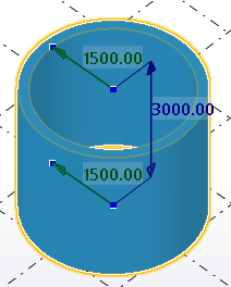
For example, if you are using two construction circles to create a lofted slab:

-
Select the second construction object:

Tekla Structures creates the lofted slab between the selected construction objects, using the Lofted slab properties in the property pane.
-
-
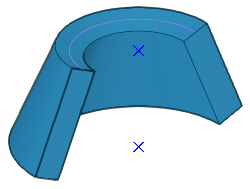
Use one construction object and a point
 to create a
lofted slab:
to create a
lofted slab: -
Select the first construction object: line, arc, circle, or polycurve.
For example, if you are using a construction polycurve and a point to create a lofted slab:
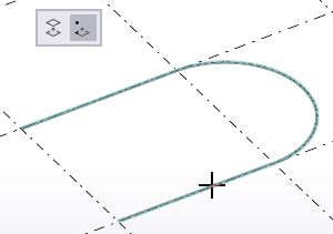
Tekla Structures shows a preview of the part geometry. Use the preview to set the direction and height of the lofted slab.
-
Pick a point.

Tekla Structures creates the lofted slab based on the preview.
-
-
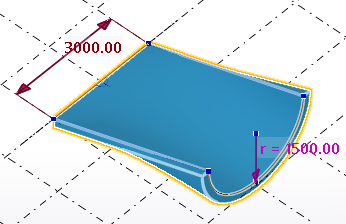
Modify the shape of a lofted slab
Use direct modification dimension handles and dimension values to modify the lofted slab shape.
-
Modify, for example, the height and radius of the lofted slab.
-
For lines and arcs: drag the arc symbol
 at the midpoint of a line or an arc to modify the lofted slab shape.
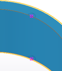
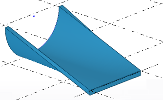
Split a lofted slab
Note that you cannot split closed cylindrical or conical lofted slabs.
-
Pick a point for the
dividing line.
Tekla Structures splits the lofted slab.
For example:
Swap the end handle points to correct the geometry of a lofted slab
In some cases when you try to create a lofted slab, the geometry of the slab would become self-intersecting, meaning that the start and end points of the top and bottom construction object are opposite of each other. In these cases the slab is not created.

You can try to resolve the situation and create the lofted slab by changing the modeling direction of the construction lines or arcs.
-
Select the construction line
or the construction arc.
With construction lines, ensure that the Direct modification
 switch is not
active. You can then see the yellow and magenta object handles.
switch is not
active. You can then see the yellow and magenta object handles. -
On the contextual toolbar,
click
 Swap ends.
Tekla Structures changes the modeling direction of the selected construction object, and the lofted slab can be created correctly.
With construction circles you can try to resolve the situation by moving either of the circles.
Modify concrete lofted slab properties
- If the property pane is not open, double-click the lofted slab to open the Lofted slab properties.
- Change the properties as needed.
- Click Modify.
Lofted slab properties
Use the Lofted slab properties in the property pane to view and modify the properties of a concrete lofted slab. To open the properties, double-click the concrete lofted slab. The file name extension of a concrete lofted slab property file is *.lsl.
If you have customized the property pane layout, the list of properties may be different.
|
Setting |
Description |
|---|---|
|
General |
|
|
Name |
User-definable name of the lofted slab. Tekla Structures uses part names in reports and in Document manager, and to identify parts of the same type. |
|
Thickness |
Thickness of the slab. |
|
Material |
Material of the lofted slab. |
|
Finish |
Type of finish. |
|
Class |
Use to group lofted slabs. For example, you can display parts of different classes in different colors. |
|
Face type |
|
|
Face type |
Select whether the top and bottom faces of the slab are flush with the plane. Perpendicular:
The top and bottom faces of the slab are non-linear. |
|
Bounded by curved planes:
The top and bottom faces of the slab are planar. |
|
|
Cast unit |
|
|
Cast unit numbering |
Part prefix and start number for the part position number. |
|
Cast unit |
Indicate whether the slab is precast or cast in place. |
|
Pour phase |
Pour phase of the cast-in-place parts. Use to separate pour objects from one another. |
|
Concrete covers for rebar sets |
|
|
Coordinate system |
Select whether the concrete cover thickness of the rebar sets in the part is defined in the global coordinate system, or in the part's local coordinate system. The default global and local cover thickness values are defined in the Options dialog box. If you select the empty option, Tekla Structures uses the global values. |
|
Top, Bottom, Sides, Front , Back, Start, End |
To override global or local default values from the Options dialog box, define the cover thickness at each required part face. |
|
More |
|
|
UDAs |
Click the User-defined attributes button to open the user-defined attributes (UDAs) of the part. UDAs provide additional information about the part. |