Concrete Stairs Tool
Not version-specific
Tekla Structures
Environment
Not environment-specific
Introduction
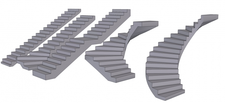
Intuitive tool for modeling concrete stairs of any common shapes.
Support for straight, L- , U- and spiral stairs.
Image
Creation
Activate the stair creation from the application and component catalog.
Image
After activating the creation, options will appear in the contextual toolbar.
Options at the top are for selecting the type of the stair:
- Straight
- L -shape
- U-shape
- Spiral
- Advanced stair (step by step)
Image

Dropdown in contextual toolbar is for the alignment of the stair to its insertion points:
- Center (middle)
- Left (Stairs are created to the left side of the picked points)
- Right (Stairs are created to the right side of the picked points)
Wrench icon opens the options of the tool
Image
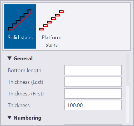
In Options there are controls for:
- Geometry type (Solid stairs or only steps)
- Bottom length
- Thickness of the first step
- Thickness of the last step
- Cover thickness ( Thickness of the stair)
- Numbering settings
- Parameters
Editing
All other editing happens with the direct modification and from the contextual toolbar.
Here are available direct modifications to a L-shape stair:
Image
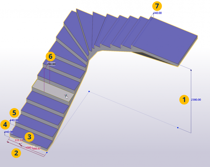
- Height
- Width
- Walk line location
- First step height
- Other step heights
- Step length for selected step
- Last step heights
In contextual toolbar you can adjust stair parameters. For L stair you will get following options:
Image
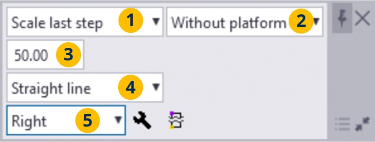
1. Flexible space of the stair
- Scale last step
- Scale step height
- Scale step lengths
2. Corner type
- Without platform
- With platform
3. Minimum step distance
4. Step length calculation method in turning stairs
5. Stair alignment
Image

If you select one individual step, you can to edits also its length or rotation. Rotate the step around the intersection with the walk line by dragging the corner handle.
Image

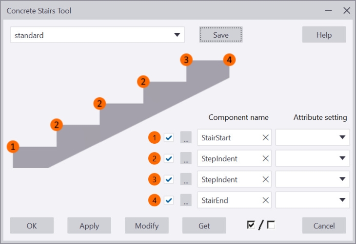
Component details
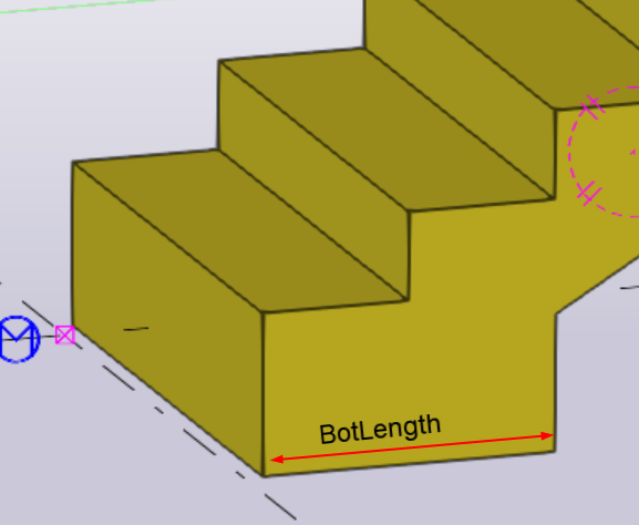
You can add sub-components to each step for additional detailing of the stair. It's recommended to create custom component as a "seam type" where input points are from right to left like shown in the picture below. You can use the stair tool to populate step height and step length to the sub-component by naming the property "StepHeight" and "StepLength".
Image

Also you can control the bottom length of the with a property name "BotLength" and the top height with name "TopHeight".
Image
After defining the sub-components, you can set those to be the details of each location like shown in the picture below.
Image
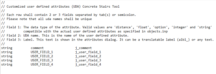
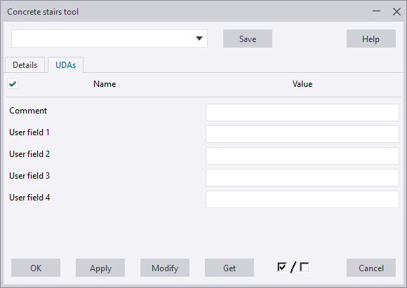
UDAs tab
You can customize the content of the UDA tab by using the ConcreteStairsTool.Udas.dat file. This file can be located in any of the folders set in the XS_FIRM, XS_PROJECT or XS_SYSTEM advanced options, or in the model folder.
The sample file shown below contains a full description of all the settings and the format of the file. The lines starting with '//' are comment lines.
Image
The image below show how the settings defined in the example file are created in the Concrete stairs tool dialog box.
Image
Tool custom extension
Extension features:
- Extensions can extend DM functionality by implementing ConcreteStairsTool.Geometry.MeshCreators.IMeshCreatorDM interface alongside ConcreteStairsTool.Geometry.MeshCreators.IMeshCreator interface.
- Extensions implement their own preview drawing.
- Extensions can define their own fields and buttons that show under the wrench icon.
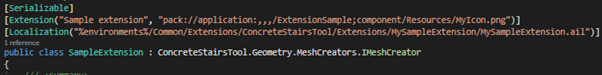
- Extensions can load their own ail file by specifying Localization attribute on the extension class (special path variables are %environments% and %messages%).
Extension creation:
New project
- Create new empty .NET Framework project.
- Add reference to ConcreteStairsTool.dll and set its “Copy Local” property to false.
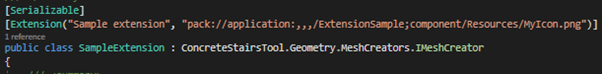
- Create a new public class that implements IMeshCreator interface and has Serializable and Extension attribute on it. First extension attribute parameter is name of the Extension that will be shown in the UI and second one is path Icon that will be show in the UI (path should be absolute URI).
Image
- To load custom AIL file for localization in the UI specify Localization attribute on the class with either absolute path, or use special path variables.
Image
- It is also possible to control how UDAs get applied to the object created by extension by using SetUdaBehaviour attribute (possible options are all parts and manual, default behaviour is all parts).
Image

- Implement methods DrawPreview() and Insert() of the interface.
- Optionally it is also possible to also implement custom direct manipulation on top of existing one by using IMeshCreatorDM.
Custom UI fields and buttons
Basic fields:
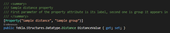
- Each value field has a property attribute. This attribute tells ConcreteStairsTool UI what label field has and in what group it appears.
Image
- We also sometimes want to define properties that will not get saved. For those we will use DoNotSave attribute.
Image
Basic supported property types:
- Tekla.Structures.Datatype.Distance
- Tekla.Structures.Datatype.DistanceList
- String
- Int
- Bool
- Double
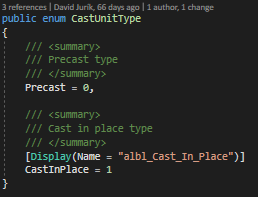
- Enum - To localize or set label of enum value in combo box use Display attribute
Image
Special property types:
Some properties can also have a special type modifier attribute as well.
- Integer properties can use PropertyAttribute.PropertyType.Class
Image
- String properties can use PropertyAttribute.PropertyType.Material
Image
Custom combo boxes:
It is also possible to define custom combo boxes bonded by index or selected value. To create these we need to use Combo box attribute and another property to hold list of combo box values.
- Create combo box property itself. If combo box is bonded by selected item, it is possible to use any object type, if it is bonded by selected index only integer type is supported.
Image
First parameter of the attribute indicates label text, second field group, third how combo box is bonded and fourth name of property containing list of items combo box will show.
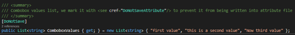
- Now we can define list of items for the combo box. If we do not want to save values of this list to the standard file, we need to use DoNotSave attribute.
Image
Custom Buttons:
- To define custom button we can use PublishedAction attribute on public void methods.
Image

First parameter is label on the left of the button, second tells ConcreteStairsTool which field group it belongs to and third sets label on the button.
- Methods with published action attribute are public, have return type void and do not take any parameters.
Extension install:
There are two possible places where extension dll can be placed. Do NOT copy ConcreteStairsTool.dll with your extension.
- Placing it directly into “<TS_Extensions_folder>/ConcreteStairsTool/Extensions/”
Use this one only if your extension is a single file contained library. - Placing it into a sub folder eg.: “<TS_Extensions_folder>/ConcreteStairsTool/Extensions/My sample extension/”
Use this one if your extension comes with multiple files (eg.: with AIL file).