Modify a rebar set using leg faces
In addition to modifying an entire rebar set, you can make changes to any individual leg face.
Show the leg faces
To modify rebar sets by using leg faces, you first need to make the leg faces visible.
-
Ensure that the
 Direct modification switch is active.
-
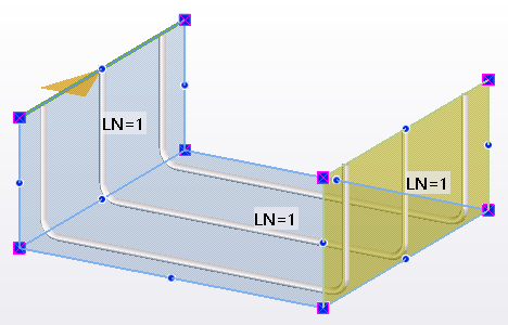
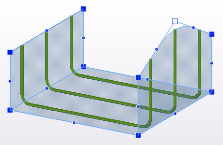
Select a rebar set.
Tekla Structures shows the leg faces. Tekla Structures also shows the bar layer numbers of the rebar set on each leg face, for example LN=1.

-
Move the mouse pointer over
a leg face and click to select it.
Tekla Structures highlights the leg face in yellow.
Alternatively, you can set the advanced option
XS_REBARSET_SHOW_LEGFACES to TRUE,
or use the keyboard shortcut Alt+1.
Modify the leg faces
You can use any of the following methods when you modify rebar set leg faces.
-
To create a new, connected
leg face, hold down Ctrl and drag an edge of the leg face.
-
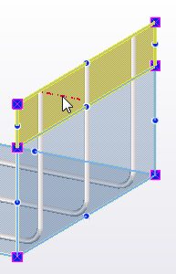
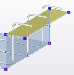
To add a new leg face at a
part face or pour object face, click
 Add leg face on the contextual tab on the ribbon, and then select the part face or
pour object face.
Add leg face on the contextual tab on the ribbon, and then select the part face or
pour object face.
-
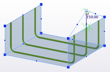
To create a new leg face on
the basis of its corner points, switch Picking mode to
 ,
click Add leg face on the contextual tab on the ribbon, and then pick points to indicate the
leg face corners. Click the middle mouse button to finish picking.
,
click Add leg face on the contextual tab on the ribbon, and then pick points to indicate the
leg face corners. Click the middle mouse button to finish picking.
-
To add a new corner point to a leg face, drag a midpoint handle.
-
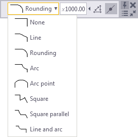
To modify a corner chamfer of a leg face, select the corner point, and then select the
chamfer type and enter the chamfer dimensions on the contextual toolbar.
-
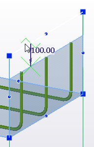
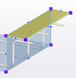
To define an additional offset between a leg face and the bars, select the leg face and enter a value for
Additional offset on the contextual toolbar, for example,
 .
.
A negative value moves the bars outside the concrete.
-
To flip bars over to the other side of a leg face, select the leg face and click
 Flip bar side on the contextual toolbar.
Note that after flipping, Tekla Structures searches for concrete on the other side of the leg face to create a concrete cover and apply the concrete cover settings. If there is no concrete, the concrete cover thickness will be zero.
-
To change the order of the
bar layers at an individual leg face, select the leg face and adjust the
layer order by using the following buttons on the contextual toolbar:
-
Click
 to move the bars to the outermost layer.
 -
Click
 to move the
bars one layer outwards.
to move the
bars one layer outwards. -
Click
 to move the
bars one layer inwards.
to move the
bars one layer inwards. -
Click
 to move the bars to the innermost layer.
Alternatively, you can enter a number in the Layer number box in the property pane, and then click Modify to save the changes.
The smaller the layer number, the closer to the concrete surface the bar layer is. You can use both positive and negative numbers.
These modifications override the layer order settings of the entire rebar set.
-
Tip:
You can modify leg face properties also in the property pane.