Add automatic marks
You can set up automatic marks for building objects (parts, neighbor parts, bolts, surface treatment, connections, reinforcement, and neighbor reinforcement) and save the mark properties in a property file for later use.
You can do this the view properties dialog box of single-part, assembly, and cast unit drawings. For general arrangement drawings, automatic marks can be defined on drawing level.
-
Do one of the following depending on the drawing type.
Drawing type Add automatic marks Single-part, assembly and cast unit drawings:
-
Click View creation in the options tree on the left, select the view and the properties that you want to change, and click View properties.
-
Click the mark type you want to modify, for example, Part mark.
-
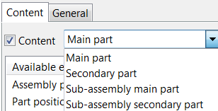
For some marks, you need to select from a list the object that you are defining the marks for.
For example, for part marks, you can define part mark settings independently for main and secondary parts, and for sub-assembly main and secondary parts.
-
Add elements in the mark by double-clicking the elements in the Available elements list.
-
Modify the element appearance (frame and font).
For length, height, spacing and diameter elements, you can adjust also the unit and format.
-
Use the Move up and Move down buttons to place the elements in the order you want.
-
Modify the appearance, placement and visibility settings on the Content and General tabs.
- Save the view properties by entering a properties file name in the box at the top and click Save.
- Click Close to return to the drawing properties.
General arrangement drawings:
-
Click the mark type you want to modify, for example, Part mark....
-
For some marks, you need to select from a list the object that you are defining the marks for.
For example, for part marks, you can define part mark settings independently for main and secondary parts, and for sub-assembly main and secondary parts.
-
Add elements in the mark by double-clicking the elements in the Available elements list.
-
Modify the element appearance (frame and font).
For length, height, spacing and diameter elements, you can adjust also the unit and format.
-
Use the Move up and Move down buttons to place the elements in the order you want.
-
Modify the appearance, placement and visibility settings on the Content and General tabs.
-
Save the mark properties by entering a properties file name in the box at the top and click Save as.
-
Click OK in the subdialog to save the changes, close the subdialog and return to the drawing properties.
-
Example
This is an example of a part mark.

- Assembly position
- Size
- Mark frame
- Profile
- Mark element frame
- Length