Rebar coupler and anchor tools
2019i
Tekla Structures
Rebar coupler and anchor tools
Rebar coupler and anchor tools is a set of four components that help to model and manage
- reinforcing bar couplers that connect two bars
- end anchors that are devices at the unreserved end of the bar.
The following components are part of Rebar coupler and anchor tools :
- Rebar coupler
- Rebar end anchor
- Split rebar and add coupler
- Rebar end trimming
In addition, you can manage the user-defined attributes (UDAs) of the Rebar coupler and anchor tools with the Update rebar attributes component.
All couplers and end anchors are automatically added to the parent part of the reinforcing bar. This allows them to be shown in reports and drawings because they are added to the sub-assembly of the cast unit.
In some cases the reinforcing bars can move outside of the concrete. This may happen with reinforcing bars that are modeled with two points (straight bars and straight bars with hooks). If the reinforcing bars move outside of the concrete, change the cover thickness to either a negative or a positive value depending on what is required.
Two report templates Rebar Extra Fabrication Length.rpt and Rebar Thread Length.rpt can be used to inquire Threaded Length and Extra Fab. Length of the reinforcing bars in the BOMs or BOQs.
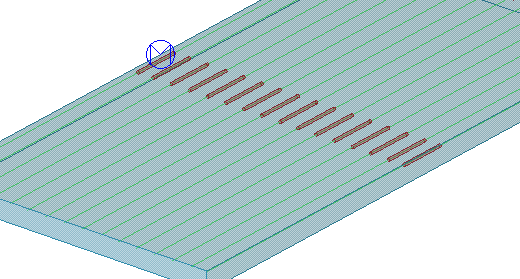
Rebar coupler
Rebar coupler creates couplers to connect reinforcing bars, or reinforcement meshes, whose bar ends are in contact and parallel.
Objects created
- Round parts
The parts are created between two reinforcement objects.
Use for
| Situation | Description |
|---|---|
| Couplers with split reinforcing bars. |
Before you start
Couplers can be created between reinforcing bars or reinforcement meshes. The selected reinforcement objects can be of different type and they can even have different number of bars. The only requirement is that one or more bar ends are in contact and parallel. With rebar sets, the couplers can only be created between spliced bars in that particular rebar set.
Selection order
| Reinforcing bars or reinforcement meshes |
|
| Rebar sets |
or
|
Couplers are created at each location where
- the bar ends are parallel enough (angle < 5 degree) and
- the gap along the bar end is less than the length of the coupler and
- the offset perpendicular to the bar end legs is less than the diameter of the bars
When there is no valid and no parallel end-to-end location between the selected bars, the component creates a dummy part that identifies the unsuccessful coupler insertion.
Parameters tab
Use the Parameters tab to define the coupler properties.
| Option | Description |
|---|---|
| Use manually entered values | Enter values for the coupler properties. |
| Use auto attribute file | The values in the auto attribute file override the coupler component values. Typically the auto attributes file contains one or more attribute values to be used with certain bar sizes. Go to Tekla Warehouse to get auto attribute files for your project. For more information on the structure of the auto attribute files, see Customize attribute files, part mapping and user-defined attributes (UDAs). |
| Option | Description |
|---|---|
| Use custom component | Select Yes to create the coupler as a custom part. Select No to create the coupler as a normal part. |
| Name | Type the name of the custom component, or select it from the Applications & components catalog. Ensure that the selected component is a custom part. |
| Attribute | Type the name of the attribute file of the custom component. The coupler custom part is created using the saved attributes given here. |
| Input points | The order of the start and the end points of the custom component. |
| Option | Description |
|---|---|
| Numbering series | Prefix and a start number for the coupler part position number. |
| Attributes | Name, diameter, material, finish and class of the coupler parts. |
| The overall end-to-end length of the coupler. If you use a custom part, this is the length between the start point and the end point of the custom part. This is also the maximum gap between the bar ends. If the gap is bigger than the length of the coupler, the coupler cannot be inserted. |

When you create the couplers as custom parts, the properties in the Numbering series and Attributes sections can be filled from the custom part settings if you have named the properties in a certain way.
Attributes tab
Use the Attributes tab to define the user-defined attributes (UDAs).
| Option | Description |
|---|---|
| Threaded length | The value is written to the reinforcing bar UDA. The fields are used for checking which bars have threads and what are the thread values so that they can be shown in drawings and reports. |
| Extra fabrication length | This value is written to the reinforcing bar UDA. This value does not affect the length of the reinforcing bar. You need to add this value in your drawings and reports to get the correct length if required. |
Method Type Product Code | UDAs written to the reinforcing bars. You can set the reinforcing bar end method and the coupler type, and add a product name and a code for reporting purposes. The used attribute name depends on which end of the reinforcing bar the coupler was created to. |
Note:
The above user-defined attributes affect numbering. Reinforcing bars with different attribute values get different part marks.
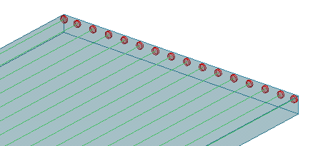
Rebar end anchor
Rebar end anchor creates end anchors at the ends of reinforcing bars or reinforcement meshes.
Objects created
- Round parts
The parts are created at reinforcing bar ends.
Use for
| Situation | Description |
|---|---|
| Reinforcing bars with end anchors. |
Selection order
| Reinforcing bars or reinforcement meshes |
|
| Rebar set bars |
or
|
Parameters tab
Use the Parameters tab to define the end anchor properties.
| Option | Description |
|---|---|
| Use manually entered values | Enter values for the end anchor properties. |
| Use auto attribute file | The values in the auto attribute file override the end anchor component values. Typically the auto attributes file contains one or more attribute values to be used with certain bar sizes. Go to Tekla Warehouse to get auto attribute files for your project. For more information on the structure of the auto attribute files, see Customize attribute files, part mapping and user-defined attributes (UDAs). |
| Option | Description |
|---|---|
| Use custom component | Select Yes to create the end anchor as a custom part. Select No to create the end anchor as a normal part. |
| Name | Type the name of the custom component, or select it from the Applications & components catalog. Ensure that the selected component is a custom part. |
| Attribute | Type the name of the attribute file of the custom component. The end anchor custom part is created using the saved attributes given here. |
| Input points | The order of the start and the end points of the custom component. |
| Option | Description |
|---|---|
| Numbering series | Prefix and a start number for the end anchor part position number. |
| Attributes | Name, diameter, material, finish and class of the end anchor parts. |
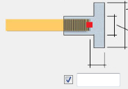
| The dimensions of the end anchor. If you use a custom part, define the length between the start point and the end point of the custom part using these values. |
| The offset of the far most point of the coupler measured from the physical end of the reinforcing bar. Note that you cannot control the end of the reinforcing bar with this component. You need to make sure the end concrete cover of the reinforcing bar is greater or equal to this offset plus the minimum concrete cover. |

When you create the end anchors as custom parts, the properties in the Numbering series and Attributes sections can be filled from the custom part settings if you have named the properties in a certain way. For an example, see Customize attribute files, part mapping and user-defined attributes (UDAs).
Attributes tab
Use the Attributes tab to define the user-defined attributes (UDAs).
| Option | Description |
|---|---|
| Threaded length | The value is written to the reinforcing bar UDA. The fields are used for checking which bars have threads and what are the thread values so that they can be shown in drawings and reports. |
| Extra fabrication length | This value is written to the reinforcing bar UDA. This value does not affect the length of the reinforcing bar. You need to add this value in your drawings and reports to get the correct length if required. |
Method Type Product Code | UDAs written to the reinforcing bars. You can set the reinforcing bar end method and the coupler type, and add a product name and a code for reporting purposes. The used attribute name depends on which end of the reinforcing bar the coupler was created to. |
Note:
The above user-defined attributes affect numbering. Reinforcing bars with different attribute values get different part marks.
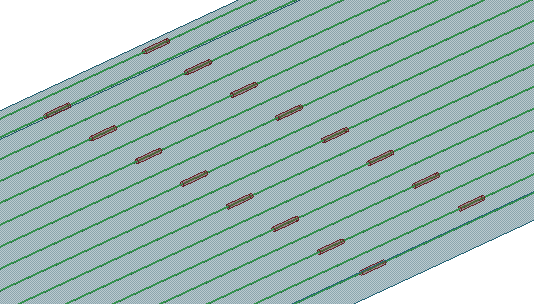
Split rebar and add coupler
Split rebar and add coupler splits a reinforcing bar group and adds couplers in relation to the direction of the picked points.
Objects created
- Round parts
The parts are connected between two reinforcing bar groups.
Use for
| Situation | Description |
|---|---|
| Staggered couplers with split reinforcing bars. |
Selection order
- Double-click Split rebar and add coupler to open the component properties.
- Click Split rebar with coupler.
- Select the reinforcing bar or bar group to be split.
- Pick the first split point.
- Pick the second split point.
This point defines the line at which the reinforcing bar or bar group is split and couplers are inserted.
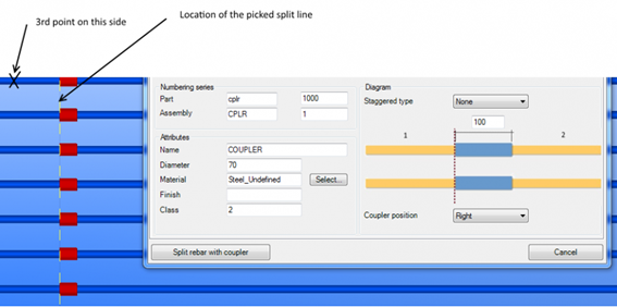
- Pick the third point.
This point defines the side of the main reinforcing bar or bar group. This is needed if you have applied different properties for the first bar or group and the second bar or group.
- Repeat the steps 3 - 6, or press Esc to cancel picking.
Parameters tab
Use the Parameters tab to define the coupler properties.
| Option | Description |
|---|---|
| Use manually entered values | Enter values for the coupler properties. |
| Use auto attribute file | The values in the auto attribute file override the coupler component values. Typically the auto attributes file contains one or more attribute values to be used with certain bar sizes. Go to Tekla Warehouse to get auto attribute files for your project. For more information on the structure of the auto attribute files, see Customize attribute files, part mapping and user-defined attributes (UDAs). |
| Option | Description |
|---|---|
| Use custom component | Select Yes to create the coupler as a custom part. Select No to create the coupler as a normal part. |
| Name | Type the name of the custom component, or select it from the Applications & components catalog. Ensure that the selected component is a custom part. |
| Attribute | Type the name of the attribute file of the custom component. The coupler custom part is created using the saved attributes given here. |
| Input points | The order of the start and the end points of the custom component. |
| Option | Description |
|---|---|
| Numbering series | Prefix and a start number for the coupler part position number. |
| Attributes | Name, diameter, material, finish and class of the coupler parts. |
| Staggered type |
|
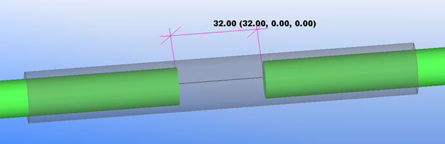
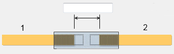
| The overall end-to-end length of the coupler. If you use a custom part, this is the length between the start point and end the point of the custom part. This is also the maximum gap between the bar ends. If the gap is bigger than the length of the coupler, the coupler cannot be inserted. |
| Coupler position | Location of the couplers in relation to the selected split line. If you select the Left or the Right option, the actual left or right depends on the third input point which defines the side of the first bar. This option is available only when there is no staggering. Example:
|

When you create the couplers as custom parts, the properties in the Numbering series and Attributes sections can be filled from the custom part settings if you have named the properties in a certain way. For an example, see Customize attribute files, part mapping and user-defined attributes (UDAs).
Attributes tab
Use the Attributes tab to define the user-defined attributes (UDAs).
| Option | Description |
|---|---|
| Threaded length | The value is written to the reinforcing bar UDA. The fields are used for checking which bars have threads and what are the thread values so that they can be shown in drawings and reports. |
| Extra fabrication length | This value is written to the reinforcing bar UDA. This value does not affect the length of the reinforcing bar. You need to add this value in your drawings and reports to get the correct length if required. |
Method Type Product Code | UDAs written to the reinforcing bars. You can set the reinforcing bar end method and the coupler type, and add a product name and a code for reporting purposes. The used attribute name depends on which end of the reinforcing bar the coupler was created to. |
Note:
The above user-defined attributes affect numbering. Reinforcing bars with different attribute values get different part marks.
Rebar end trimming
Rebar end trimming adjusts the space between two reinforcing bar ends.
Use for
| Situation | Description |
|---|---|
| Space between reinforcing bar ends. |
Selection order
- Select the couplers you want to modify.
- Modify the properties.
- Click Apply to selected couplers.
OR
- Modify the properties.
- Click Select rebars.
- Select the reinforcing bars whose ends are adjusted according to the value set for the gap.
Rebar coupler/Rebar end anchor tab
| Option | Description |
|---|---|
| Get free gap from auto attributes file | Select Yes if you want to use the gap defined in the Auto attribute file for the couplers. When you select Yes , only the coupler components that have the Use auto attribute file in use are adjusted. See Customize attribute files, part mapping and user-defined attributes (UDAs). Select No if you want to manually enter the free gap. |
| The gap when Get free gap from auto attributes file is set to No. |
| Trim both bars | Select which of the reinforcing bars is modified. |
| Apply to selected couplers | Select the couplers you want to modify and click the Apply to selected couplers button to adjust the bars according to the value set for the gap. |
| Select rebars | Click the Select rebars button and select the reinforcing bars whose ends you want to adjust according to the value set for the gap. The reinforcing bar ends need to be close to each other. |
Update rebar attributes
Use Update rebar attributes to manage the user-defined attributes (UDAs) of the couplers and the end anchor parts created by the Rebar Coupler and Anchor Tools. With Update rebar attributes you can check the current values of the selected reinforcing bars or all reinforcing bars.
If you have added coupler or end anchor components to reinforcing bars, the UDA values are controlled by the coupler or the end anchor components and their properties. If you delete the coupler or the end anchor component, the UDAs defined by those components are not cleared automatically. Use Update rebar attributes to clear the obsolete attribute values.
| Option | Description |
|---|---|
| Selected | The values of all coupler and end anchor UDAs of the selected reinforcing bars in the model. |
| All | The values of all coupler and end anchor UDAs of all reinforcing bars in the model. |
| Update | Deletes the values of all coupler and end anchor UDAs of all reinforcing bars on the selected rows. Only the obsolete coupler UDAs of the reinforcing bar are deleted. You can select multiple rows by holding down Ctrl or Shift. |
| Show only rebar with attributes | Select this check box if you want to show only reinforcing bars that have values in their coupler or end anchor UDAs. After you have selected the check box, click Selected or All to refresh the table. |
Customize attribute files, part mapping and user-defined attributes (UDAs)
Auto attribute files
The attribute table files are text files that can locate in any of the system folders, or in a model folder. You can have as many attribute table files as you need. There are different attribute tables for end anchors (one input reinforcing bar) and coupler components (two input reinforcing bars). The extensions for attribute table files are
.couplers.csv for Rebar coupler and Split rebar and add coupler components
.anchors.csv for Rebar end anchor component.
The attribute table contains a header line, including the column names and one or more table rows containing the attribute values. Columns are either selector columns or attribute columns.
The selector column names are Primary.Size , Primary.Grade , Secondary.Size , and Secondary.Grade.
The attribute columns contain the attribute value that is the name given in the header row. The component attribute values given in the table row are used whenever the component input (primary + secondary for Rebar coupler and secondary for Rebar end anchor ) matches with the selector values.
Go to Tekla Warehouse to get auto attribute files for your project.
Custom part mapping
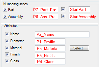
When you create the coupler or the end anchors as custom parts, the properties in the Numbering series and Attributes sections can be filled from the custom part settings if you have named the properties in a certain way. The following example shows the mapping between the Numbering series and Attributes properties and the custom part properties.
User-defined attributes (UDAs)
You can customize the content of the Attributes tab and the UDAs in the Rebar Coupler and Anchor Tools components.
The UDAs are defined in a text file named RebarCoupler.Udas.dat , located in the ...\ProgramData\Trimble\Tekla Structures\<version>\Environments\Common\system folder. The file can also be placed in some other system folder or in a firm folder. Note that the file is not read from the model folder.
The RebarCoupler.Udas.dat file only defines which UDAs are shown on the Attributes tab. If you modify the file, include only existing UDAs to the file. If you want to create new UDAs, ensure that you define them properly.
Note:
The UDAs affect numbering if the UDAs' special numbering flag ( special_flag ) is set to yes in the objects_couplers.inp file. Reinforcing bars with different UDA values will then get different part marks.