Add frames and fold marks in printouts

Tekla Structures
2019i
Tekla Structures
Frames
foldmarks
fold marks

Add frames and fold marks in printouts

You can add frames and fold marks in printed drawings. Fold marks indicate the locations where the printouts should be folded. You can select a color for the frames and fold marks.

Drawing frames and fold marks are controlled in the standard.fms file under the \system folder. There is no saving option in the Drawing Frame Properties dialog box, which is why the default values are located in a standard file. You can save the standard file in the model folder, and then copy it to the project or firm folders, if needed. If you want to save a set of standard files in the model folder, see Standard files.

  1. Go to the Print Drawings dialog box by selecting File > Print drawings , for example.
  2. Click the Frames button.

    The command Drawing frames and fold marks is also available in Quick Launch.

  3. In the Drawing Frame Properties dialog box, select the check boxes of the frames you want to print.
  4. In Margins , enter in millimeters the distance between each frame and the left, right, bottom, and top edge of the paper.
  5. Select a color for each frame.
  6. To print the fold marks, select the Foldmarks check box.
  7. Enter in millimeters the horizontal and vertical distances of the first fold marks from the lower right corner of the outer frame, and between the other fold mark.
  8. Select a color for the fold marks.
  9. Click OK.

    These settings are for the model and impact all drawings.

    If you have a drawing open while you adjust the frames and fold marks, you need to reopen the drawing to activate the changes. If you change the frame and fold mark settings for the drawing that is shown in the Print Drawings dialog box preview, the preview does not update, and you need to reopen the dialog box to see the changes in the preview.

Below is an example of the properties dialog box contents and the standard file.
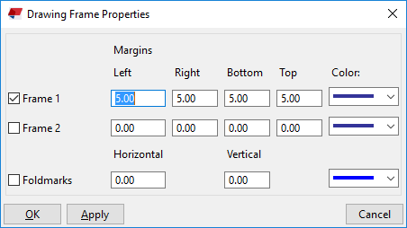
Note:

There is a fixed distance value of 5 mm in drawing frame margins. Thus, if you want to use a drawing frame margin with a drawing title that sticks to the frame corner, you need to change not only the drawing frame margin in the Drawing Frame Properties dialog box, but also the Vector between corners in the Tables dialog box ( Drawings & reports > Drawing properties > Drawing layout editor > Table layout... > Tables... ).

Was this helpful?
Previous
Next