Show neighbor parts in drawings

Tekla Structures
2019
Tekla Structures

Show neighbor parts in drawings

You can select which neighbor parts to show in drawings and also automatically extend the view boundary if necessary.

Neighbor parts refer to (optionally shown) parts that are close to the part that is depicted in a drawing. Depending on settings, the neighbor parts may be parts somehow connected to the part in question, or just parts that happen to be close by.

For more information about neighbor part properties, see Part and neighbor part properties in drawings.

Tip:

If you do not want to see neighbor part extensions in drawing views, set the advanced option XS_VISUALIZE_VIEW_NEIGHBOR_PART_EXTENSION to FALSE.

Show neighbor parts in assembly and cast unit drawings

  1. On the Drawings & reports tab, click Drawing properties and select the drawing type.
  2. Load drawing properties that are as close to the ones you need as possible.
  3. Click View creation in the options tree on the left, select the view and the properties that you want to change, and click View properties.
  4. Click Neighbor part...
  5. On the Visibility tab, select the parts and that you want to show using the following options:
    • None does not show neighbor parts.

    • Connected parts shows all parts connected to the model object.

    • Connecting parts shows only the parts the model object is connected to.

    • All components combines the Connected parts and the Connecting parts options.

    • By extreme show all parts within the boundaries of the main and secondary part. This setting is affected by the value entered for View extension for neighbor parts on the Attributes 1 tab.

    • Main/Secondary parts : Main parts shows only neighbor parts that make the main part of an assembly or a cast unit.

    • Main/Secondary parts : Secondary parts shows only neighbor parts that are secondary parts of an assembly or a cast unit.

    • Main/Secondary parts : Both shows both main and secondary parts.

    • Skew parts : Yes shows skew parts as neighbor parts in the drawing, No does not show skew parts as neighbor parts.

    • Bolts : Yes shows the bolts in the neighbor parts, whereas No does not show the neighbor part bolts.

  6. On the Content tab, set the representation of the neighbor part and neighbor part bolts, and which lines and marks are shown
  7. On the Appearance tab, set the colors and line types you want to use in neighbor parts.
  8. Click Attributes in the options tree and enter a value by which to extend the view in the View extension for neighbor parts box.

    Try different values and check which one suits your needs. Often too big values do not work very well. If you set the value to 0 , neighbor part extension is not shown.

    For more information about view properties, see View properties in drawings.

  9. To save the changes, click Save.
  10. Click Close to return to drawing properties.
  11. Click Save to save the drawing properties, then click OK and create the drawing.

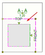
In the following example, View extension for neighbor parts is set to 100. No neighbor parts are located in this area.

Show neighbor parts in general arrangement drawings

In GA drawings, you need to define neighbor parts using neighbor part filters because neighbor parts are not automatically detected. The parts that fulfill the filtering criteria will be treated as neighbor parts. You must also define a filter for normal parts to get neighbor parts working.

  1. On the Drawings & reports tab, click Drawing properties > GA drawing .
  2. Load drawing properties that are as close to the ones you need as possible.
  3. Go to the General - Filter Properties dialog box and create a filter by Part - Name and Object - Object type for all parts that should be treated as normal parts and click OK.
  4. Go to the General - Part Properties dialog box, and on the Content , Appearance Fill tabs, define the needed part properties. For example, select a fill that shows the normal parts in a different way than the neighbor parts. Then OK.
  5. Go to the General - Neighbor Part Filter Properties dialog box, create a filter by Part - Name and Object - Object type for all parts that should be treated as neighbor parts and click OK.
  6. Go to the General - Neighbor Part Properties dialog box, and on the Visibility tab, select By extreme to show all parts within the boundaries of the main and secondary part. This setting is affected by the value entered for View extension for neighbor parts on the Attributes 1 tab.

    None does not show neighbor parts.

  7. On the Content , Appearance and Fill tabs, define the needed part properties. For example, select a fill that shows the neighbor parts in a different way than the normal parts. Then OK.
  8. Click View... , and on the Attributes tab, enter a value by which to extend the view in the View extension for neighbor parts box.

    Try different values and check which one suits your needs. Often too big values do not work very well. If you set the value to 0 , neighbor part extension is not shown.

    For more information about view properties, see View properties in drawings.

  9. Click OK to return to drawing properties.
  10. Click Save to save the drawing properties, then click OK and create the drawing.
Was this helpful?
Previous
Next