Edge chamfers in drawings
2019
Tekla Structures
Edge chamfers in drawings
You can show edge chamfers in drawings, and control the way they are shown by modifying the part properties and the edge chamfer properties. You can also add chamfer marks as associative notes.
Show edge chamfers in a drawing
You can select whether to show edge chamfers in your drawing, and the way they are shown.
- Select Outline or Exact in the Representation list depending on the desired result.
Exact

Outline

Define default line color and type for edge chamfers
You can define a default color and line type for edge chamfers in drawings.
- On the File menu, click and go to the Drawing objects settings.
- Define the default line color.
- Define the default line type.
- Click OK to save and close the dialog box.
Tip:
You can override the default settings manually in a drawing by changing the edge chamfer line color and type in the Edge Chamfer Properties dialog box.
Change edge chamfer line color and type manually
You can change the line type and color of the edge chamfers in an open drawing. This overrides the default color and type defined in the Options dialog box.
- Select the desired color and line type.
Background color
 is often used for edge chamfer lines for the reason that you may not want to print edge chamfers, or see them in small scale drawings, but you want to be able select them, for example, to add chamfer marks.
Example
The following examples show how the edge chamfers are displayed with different part representation settings:
Part representation Exact. |
|
Part representation Outline , edge chamfer not selected. |
|
Part representation Outline , edge chamfer selected. |
|


Add associative notes to edge chamfers
You can add associative notes to edge chamfers.
- Click the edge chamfer.
If you use a leader line, you need to pick a position for the note.

Example: Edge chamfers
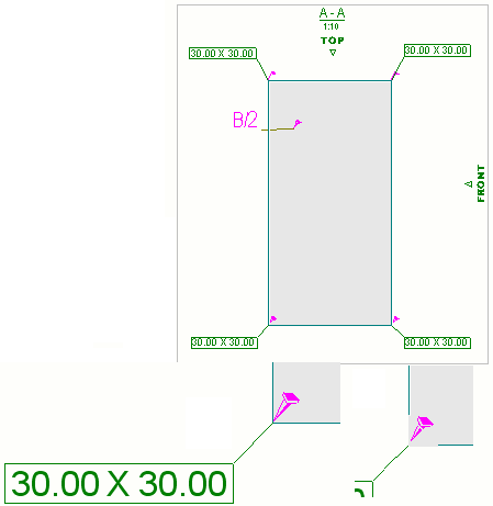
See below for typical examples of the ways showing edge chamfers.
In this example, Representation is Exact and Edge chamfers are On. Background color is used in edge chamfer lines, because you usually do not want to show edge chamfers in printouts, but may want to see and select them in the drawing, for example, to add associative notes.
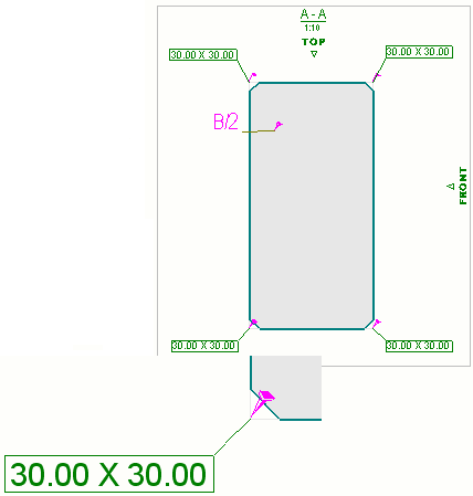
In this second example, Representation is Outline and Edge chamfers are On. Background color is used in edge chamfer lines, because you may want to see and select chamfers in the drawing, for example, to add associative notes.This representation is often used when the scale is small and you do not need to see the small chamfers clearly. The edge chamfer presented in the bottom right corner of the image shows what the edge chamfer looks like when it is selected.