Create a section view

Tekla Structures
2019
Tekla Structures

Create a section view

You can create section views of the parts in a drawing view in an open drawing that contains at least one view.

  1. Set the section mark properties first: On the Drawing tab, click Properties > Section mark .
  2. Modify the cutting line, section mark, and section view label properties in the Section Mark Properties dialog box, and click OK or Apply.
  3. Next, set the section view properties: Hold down Shift and on the Views tab, click Section view.
  4. Modify the view properties as required, and click OK or Apply.
  5. Pick two points to define the position of the section plane.

    It is easier to pick the points if you activate orthogonal snapping: On the File menu, click Settings and select Ortho or press O.

    For beams, you can also try picking the top line of the beam and then the bottom line of the beam using the snap switch Snap to perpendicular points.

  6. Pick two points to define the direction of the cut box and the section view depth.

    When you pick the cut box, exaggerate a little. You ca adjust the view depth and the view boundary also later on.

    The direction of the section is the direction where the section mark arrows are pointing.

  7. Pick the position for the section view.

    A view symbol follows the mouse pointer allowing you to see where you are about to place the section view.

    The depth to the opposite direction is zero (0).

    Tekla Structures creates the section view using the current properties in the View Properties and Section Mark Properties dialog boxes and adds a section mark in the original view. You can change the properties after creating the view.

    Tip:
    • The view boundary of the created section view remains selected, and you can adjust the depth and the height of the view boundary by dragging it.

    • If necessary, change the view scale of the section view: Double-click the view frame, clear all other selections using the toggle switch at the bottom, select only the Scale option, and adjust the scale.

    • If you want to create another view, start the Section view command again.

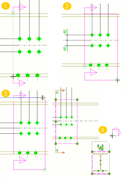
(1) The first two picked points indicate the position of the section plane.

(2) The third picked point indicates the direction of the cut box and the depth of the section view. Here you can exaggerate a little.

(3) The fourth pick finalizes the cut box.

(4) A view symbol follows the mouse pointer while you are placing the section view. The section view is placed in the selected location. The section view remains selected and the view boundary highlighted right after the view creation.

The section mark is drawn in the original view. The view boundary of the section view is also highlighted in the original view right after the view creation.

Was this helpful?
Previous
Next