Add dimensions to reinforcement
2019
Tekla Structures
Add dimensions to reinforcement
You can manually add dimension lines and dimension marks to reinforcing bar groups. When adding dimensions, start by using predefined dimension settings defined for your environment, and modify these settings for individual dimensions, if necessary. There are reinforcement dimension settings affecting the whole model in the Options dialog box.
In addition to the rebar dimensioning methods described below, you can also dimension rebars by using the Rebar group dimensioning application, see Dimension rebars with Rebar group dimensioning application.
Add dimension marks or dimension tags to rebar groups
Each reinforcing bar group may have a dimension mark or a tagged dimension mark. These dimensions are created based on predefined dimension properties that you have selected in . The commands are available in GA drawings and cast unit drawings. You may want to add reinforcement dimension marks or tagged dimension marks especially in concrete cast unit drawings, where there is only one reinforced cast unit visible.
To add dimension marks or tagged dimension marks to rebar groups:
- In an open drawing, right-click the reinforcing bar group and select one of the following dimension mark commands and pick a location for the dimension:
.
.
You can change the representation of the current rebar dimension after creating it by double-clicking the rebar dimension in an open drawing, and modifying the dimension content , appearance , and marks and tags as required. For example, you may want to add more tags, change dimension mark content, or select how to align tags in curved dimensions.
Add dimension lines to rebar groups
The Create dimension line command shows the distribution of the rebars in the group, and draws dashed lines from the dimension lines to the rebars when you drag the dimension outside the rebar group. This command is available in GA drawings and cast unit drawings, but you may want to use it especially in GA reinforcement drawings, because they may contain a lot of parts with rebar groups, and you often need to show only one rebar from the group and drag the dimension line to a proper place to see everything clearly. This command creates dimensions based on the predefined dimension properties that you have selected in .
To add dimension lines showing the distribution of the reinforcing bars to rebar groups:
- You can drag the reinforcement dimension line out of the reinforcement bar group.
When you do this, Tekla Structures draws a dashed line from the reinforcing bar to the dimension line. If the new location is in the reinforcement area, the dimension mark follows the intersection of the reinforcement bar and reinforcement dimension line.
To change the representation of the current rebar dimension, double-click the rebar dimension in an open drawing, and modify the dimension content , appearance , and marks and tags as required.
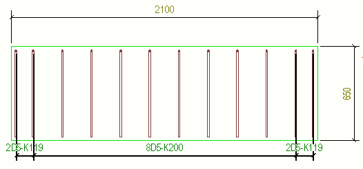
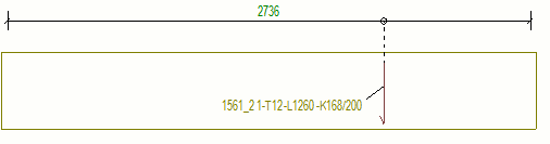
Below is an example of a dimension line created with Create dimension line :
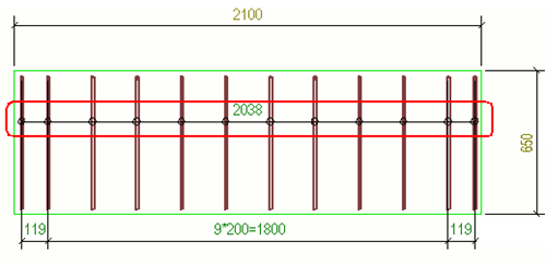
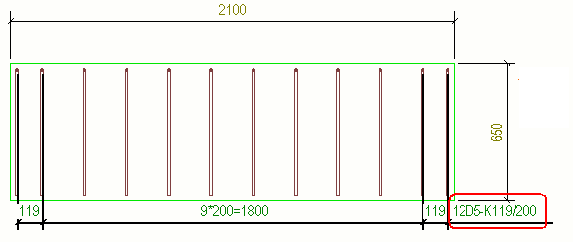
Below is an example of the dimension line when it has been dragged outside the reinforcing bar group:
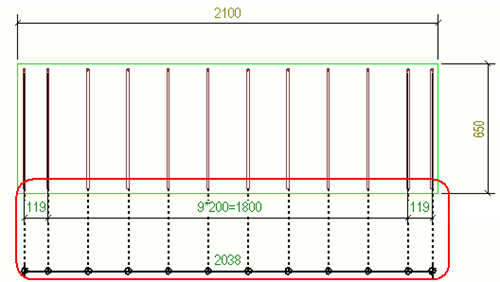
Below is an example, where only one rebar of the group is visible, and the dimension line has been dragged outside the group.
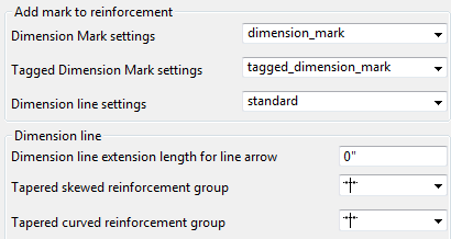
Predefined reinforcement dimension settings in the Options dialog box
There are predefined settings in the Options dialog box in the Drawing dimensions settings affecting rebar dimensions and dimension marks. Settings are model specific and only affect the current model. Changing the settings does not require Tekla Structures restart.
| Option | Description |
|---|---|
| Dimension mark settings | Select which predefined dimension settings you always want to apply to dimension marks. These settings are used when you create dimension marks with the command. |
| Tagged dimension mark settings | Select which predefined dimension settings you always want to apply to tagged dimension marks. These settings are used when you create dimension marks with the command. |
| Dimension line settings | Select which predefined dimension settings you always want to apply to dimension lines that you create with the Create dimension line command. |
| Dimension line extension length for line arrow | You can create line extensions in dimensions that have line arrows. Enter the length of the dimension line extension in the Dimension line extension length for line arrow box. This setting will be applied to all dimension that have line arrows. No extension Extension added |
| Tapered skewed reinforcement group | Select whether skewed dimensions have skewed or horizontal representation in Tapered skewed reinforcement group  . . |
| Tapered curved reinforcement group | Select whether curved dimensions have curved or horizontal representation in Tapered curved reinforcement group  . . |

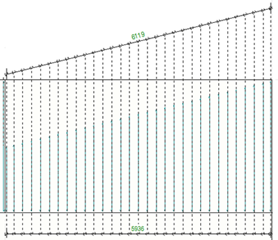
Examples of rebar dimensions
- Below is a tapered skewed part, and skewed dimension representation is selected from Tapered skewed reinforcement group. The dimension line follows the shape of the edge that is closest to where you pick.
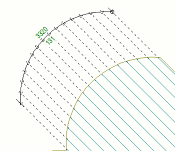
- Below is a tapered curved part, and curved dimension representation is selected from Tapered curved reinforcement group :

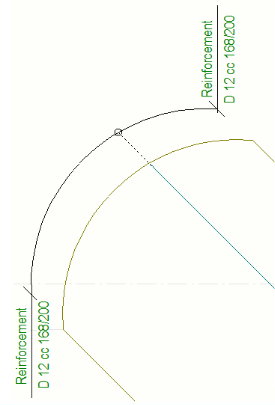
Below is an example of curved orthogonal dimensions of a tapered curved rebar group with a dimension tag:

You can also add middle tags in rebar dimensions. Here dual dimensions have been applied:
Curved dimension tags can be aligned by selecting one of the options in the Curved Dimension Tag Type list in the Dimension Properties dialog box:

In the example below, only one rebar is visible, and rebar tags are aligned vertically
 :
:
In the example below, the dimension tag follows the dimension curve
 :
:
Below is an example of curved orthogonal dimensions of a radial reinforcing bar group.
