Add automatic view-level dimensions
2019
Tekla Structures
Add automatic view-level dimensions
The next examples will go through the basic workflow of creating automatic dimensions on view level. The goal is to create drawing properties that you can use later on to create similar drawings, including all necessary views, having the dimensions that you want, just by loading the appropriate drawing properties file and then creating the drawing.
If you want to use Integrated dimensions, see Add automatic view-specific dimensions using dimensioning type Integrated , or dimension spiral beams, see Dimension spiral beams.
The workflow consists of four tasks:
- Create drawing properties
- Define drawing views and drawing view settings
- Define dimensioning rules
- Create and apply dimensioning rule properties
Define the drawing properties file
Create a drawing properties file that will pull together all the settings that you define in drawing properties, including view-level dimension settings.
Now you have created a drawing properties file where you can save the new dimensioning settings.
Define the drawing views to be created
Create the desired views and define the view properties to use:
- In the next panel, click Add row to add new views in your drawing.
Now you have defined the views that you want to have in the drawing you will create. You can save the list of views using Save , and then load it if you need the same set of views in another drawing.
Define view dimensions
Define the dimensioning rule properties to be used in the drawing views that you just created.
If you are planning to use filters to select the parts that you want to dimension, you need to create the drawing view filters first, for example, for selecting embeds, inner panels or outer panels.
You need to create separate dimensioning rules for each dimensioning type. For example, the rules made with Overall dimensions are valid for Overall dimensions only, not for Shape dimensions , for example.
- Select the Dimensioning type for the selected rules.
Here we select overall dimensions and hole dimensions:

- Depending on the selected dimensioning type, a specific Dimensioning rule properties dialog box is displayed. Do one of the following:
For most of the dimensioning types, you need to define what to dimension, and where and how to place the dimensions. From the Dimension properties list, select a suitable set of saved dimension properties to change the dimension appearance, dimension text font size or color, for example. If you want, you can define different dimension line properties for each side by deselecting Same on all sides and selecting different dimension properties.

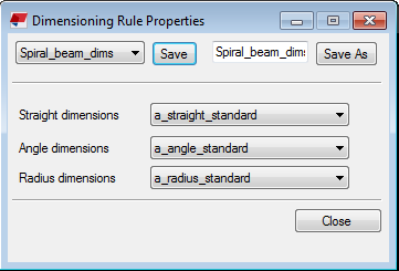
- If you have selected dimensioning type Spiral beam dimensions , select predefined dimension properties. If none of the available properties suit your needs, open a drawing, click when a drawing is open, and edit and save the needed dimension properties so that they are available for selecting in the spiral beam Dimensioning rule properties dialog box for the three dimension types.
- Select correct properties for the rules.
Even though the dimension lines are created and placed by default in the order that you define them in the View creation panel, Tekla Structures searches for the first suitable location for the dimension lines according to the placement and protection settings. So the dimension placement may not always follow the creation order. Check the result and adjust the location of the dimension lines if necessary.
Now you have created new view properties containing two types of dimensions. You can connect this properties file with a drawing view and use the defined dimensions in that view.
Connect view properties to views and save drawing properties
Connect then new view properties to drawing views and save drawing properties.
- In the View creation panel, select correct view properties for the views that you are creating.
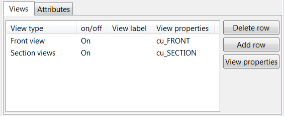
In the example below, one front view and one section view are created, and the views have been connected to view properties cu_FRONT and cu_SECTION.
Tekla Structures creates the drawing according to the definitions in various properties files.
Example workflow: Create automatic overall and hole dimensions on view level
In this example workflow, you will create a cast unit wall panel drawing that contains
- one front view with automatic overall and hole dimensions
- one section view with overall dimensions
In overall and hole dimension rules you will apply the dimension properties that you have earlier created and saved manually in a cast unit drawing. You will save the created dimensioning rule properties in view properties. Finally, you will save the created view properties in drawing properties and create a cast unit drawing.
Before starting, create manually in the object-level ’ dialog box in an open cast unit drawing a dimension properties file dim_font_5 , where the dimension text font size is 5.00 , and a dimension properties file dim_red , where the dimension color is red.
In this example, you are going to dimension the following cast unit wall panel in the model:

Define the views to be created
On the Drawings & reports tab, click .
- Load drawing properties that are as close to the ones you need as possible.
Click View creation in the options tree.
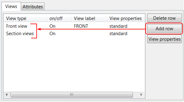
In the View creation panel, click Add row to add new views in your drawing.
In this example, you want to add two views, one front view and one section view.
Set the on/off setting to On for the views that you want to create.
If the list contains extra views, set them to Off or use the Delete row button to delete them.
Now you have defined the views that you want to create. Next, you need to define the dimensions that you want to have in the front view and section view.
Define front view dimensions
Select a view in the View creation list.
In this example, select one Front view.
Click View properties and then click Dimensioning in the option tree to define the dimensions to be created in the front view.
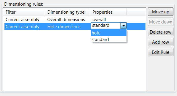
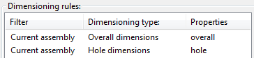
In the Dimensioning panel, use Add row to add two new dimension rules in the dimensioning rules list.
Select Overall dimensions as the first rule and Hole dimensions as the second.
The order of the rules in the list defines the order of the dimension lines in the drawing: the dimensions created by the first rule is placed closest to the dimensioned part.
Leave Current assembly in the Filter column for both rules.
To the define overall dimension rules, click the Overall dimensions row, and click Edit rule.
In the Dimensioning rule properties dialog box, define what to dimension, where and how to place the dimensions, and which dimension properties to use.
Select the check boxes above and on left side of the object, and also the check box in the upper-left corner to link the dimensions together.
Use default values in the Start point lists. The default values are left for the Horizontal and bottom for the Vertical dimension.
From the Dimension properties list, select a suitable set of saved dimension properties. In this example, select the dimension properties file dim_font_5 , which contains a definition for a larger font.
Give the dimensioning rule a unique name and click Save As.
In this example, the name overall is used.
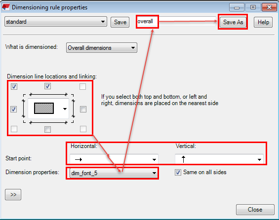
Click Close.
Next, define the hole dimensions. In the Dimensioning panel, select Hole dimensions from the dimensioning rules list and click Edit rule.
Create dimensioning rules for hole dimensions:
Select the check boxes above and on left side of the object, and also the check box in the upper-left corner to link the dimensions together.
Use the default values in the Start point lists.
In Close lines , select the setting that extends the dimension lines to the other end of the cast unit.
In Dimension to , select the setting that dimensions to both ends.
From the Dimension properties list, select a suitable set of saved dimension properties. In this example, select the dimension properties file dim_red containing a definition for red dimensions.
Give the hole dimensioning rule a unique name and click Save As.
In this example, the name hole is used.
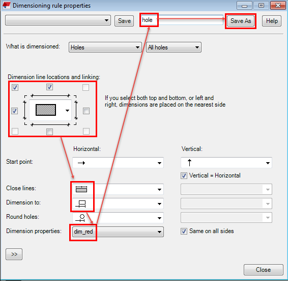
Click Close.
For the Overall dimensions rule, select overall properties, and for the Hole dimensions rule, select hole properties from the Properties column.
In the View Properties dialog box, give the front view properties a unique name and click Save.
In this example, the front view properties are saved with the name CU_Front.
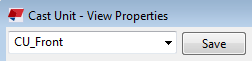
Now you have saved the view properties for the front view containing overall and hole dimensions. Leave the View Properties dialog box open for further modifications.
Define section view dimensions
A section view is also needed in the cast unit drawing, because you want to show the wall thickness. Next, you will create overall dimensions for the section view.
In the View creation panel, select the Section views row and click View properties.
Load the view properties file CU_Front.
You can start creating new view properties on the basis of already existing view properties.
Click Dimensioning in the options tree.
In the Dimensioning panel, delete the unnecessary hole dimension rule by clicking the Hole dimensions row and Delete row.
You will only need the overall dimensions in the section view.
Click the Overall dimensions row and click Edit rule.
Create a dimensioning rule for the overall dimensions in the section view:
Select the check box below the object only, because you only want to show the thickness.
Select the same dimension properties as for the overall dimensions in the front view, because you want to show the dimension text with a little bit larger font: dim_font_5.
Give the rule a unique name and click Save As.
In this example, the name thickness is used.
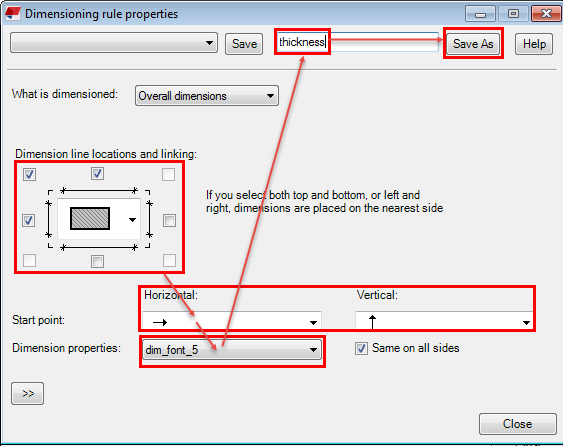
Click Close.
In the Dimensioning panel, select thickness in the Properties column as the property file for the overall dimensioning rule.
Give a unique name for the section view properties and click Save As.
In this example, the name CU_Section is used.
Click OK.
Now you have saved the view properties for the section view containing overall dimensions.
Connect view properties to views and save drawing properties
In the View creation panel, select CU_Front for the front view and CU_Section for the section view .

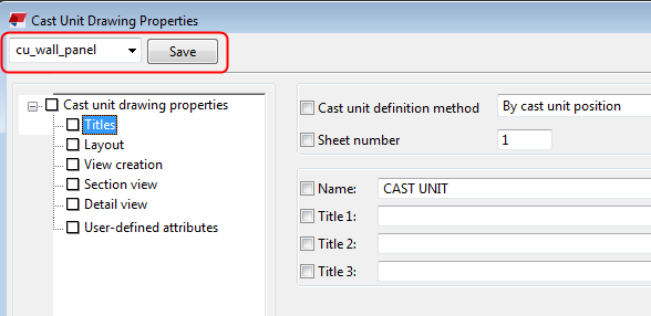
In the Drawing Properties dialog box, give the drawing properties a unique name and click Save.
In this example, the name cu_wall_panel is used.
Click OK and create the cast unit drawing.
Tekla Structures creates the cast unit drawing according your definitions in different properties files. The cast unit drawing contains a front view and a section view. The overall dimensions in both views have a little bit larger font, and the front view has red hole dimensions. Only the wall thickness is dimensioned in the section view.
You can use the drawing properties file cu_wall_panel later on when you need drawings with similar settings.

Tip:
You can still change the dimensioning settings in the views after creating the cast unit drawing:
Double-click the drawing view frame to open the view properties dialog box.
Click Dimensioning in the options tree to open the Dimensioning panel where you can select and then edit the dimensioning rules.